


Page 3
INSTALLATION OF THE VENT TERMINATION COMBUSTION AIR TEE
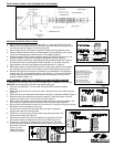
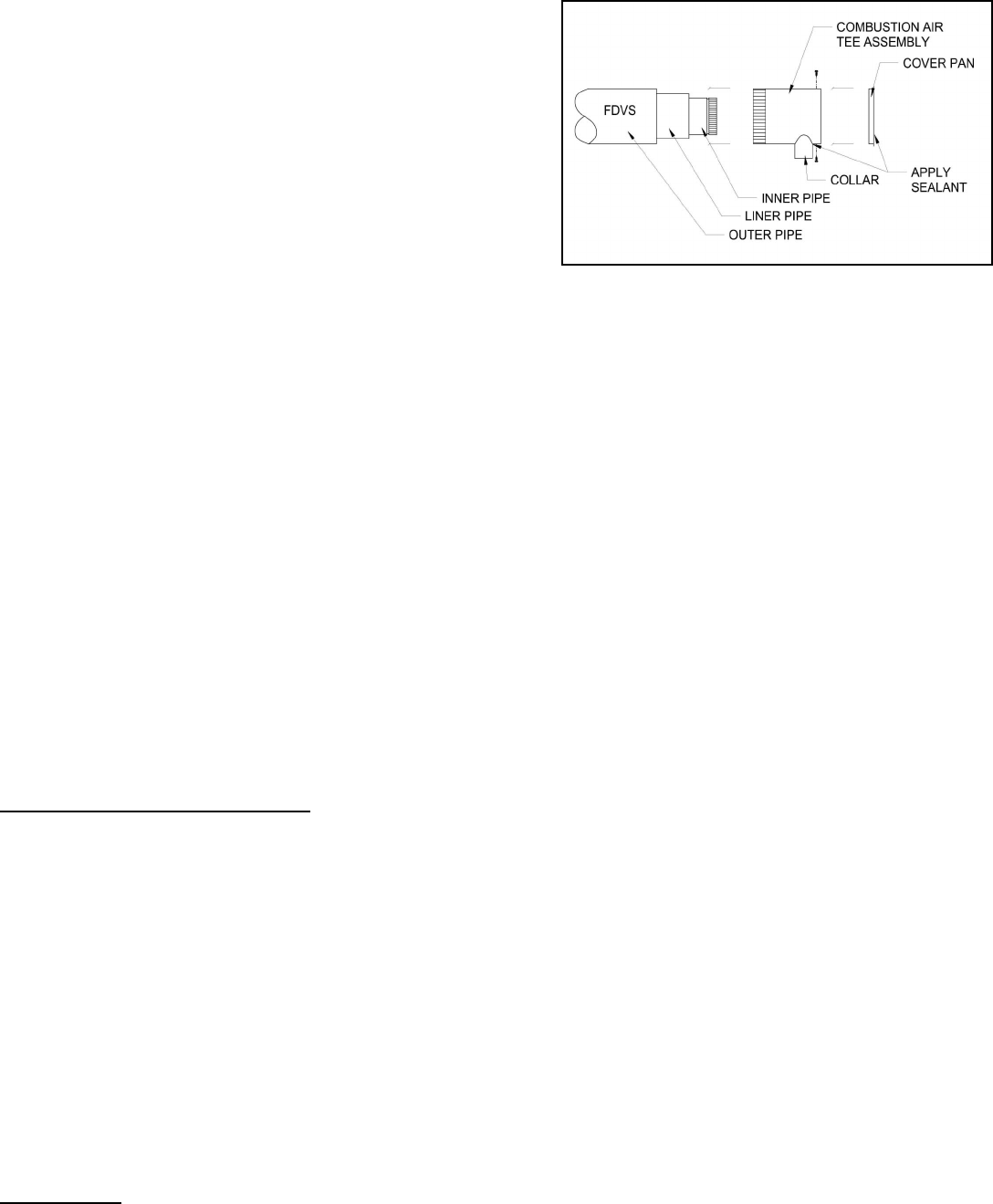
1. Assemble the combustion air tee assembly body to the vent
termination outer pipe, and rotate to the desired position. Attach the
tee assembly body to the vent termination outer pipe with at least 3
sheet metal screws evenly spaced apart (not included).
2. After completing assembly of the vent pipe to the termination inner
pipe (Fig. 4), apply the supplied high temperature sealant to the
cover pan around the inner pipe, around the joint between the collar
and the Tee assembly, and seal or tape the joint from the FDVS
Termination to the Tee assembly.
NOTE: The tee may be rotated into any position so that the collar is in a
convenient orientation.
CLEARANCE TO COMBUSTIBLES: FDVS Termination: 0", FOVP
Flexible Oil Vent Pipe: 1". These clearances are to maintained unless
superceded by the appliance manufacturer's installation instructions or by
National and/or local codes (see Step 3).
C
ONNECTING THE VENT PIPE FROM THE FDVS TO THE APPLIANCE
1. The venting system should be installed and supported in accordance with the latest version in the USA of the National Fuel Gas
Code ANSI Z223.1, UL-726, National Fire Protection Association NFPA31, and in Canada CSA B140, CSA B139 Installation Code
or in accordance with any other local codes or the authority having jurisdiction. Where requirements for venting differ the most
stringent standard requirements shall apply. A vent pipe connector, designed for positive pressure venting, shall be supported for
the design and weight of the material employed, to maintain clearances, prevent physical damage and separation of joints. All joints
MUST be sealed, for positive vent pressure, to prevent flue gas leakage into the structure.
2. Route the vent pipe from the appliance to the vent termination using the minimum number of bends as possible. The last horizontal
section of the vent pipe should have a slight downward slope from the appliance to the vent termination. For clearances to
combustible materials and other installation requirements, refer to the National Fuel Gas Code ANSI Z223.1, UL-726, NFPA31,
CSA B140, CSA B139 and/or any applicable local codes or appliance manufacturer's installation instructions.
3. Refer to the appliance manufacturer’s specifications for maximum length of vent pipe run. Unless otherwise specified by the
appliance manufacturer, use the same size diameter pipe as the exhaust outlet on the appliance to connect to the vent termination
inlet. Use a reducer or increaser, if necessary, at the vent termination to connect the vent pipe.
4. Support the Flexible Oil Vent Pipe (FOVP) at regular intervals of maximum 36" spacing with appropriate strapping or hangers, per
National and local code requirements. Do not install screws into or otherwise penetrate any part of the vent pipe under any
circumstances.
C
ONNECTING THE COMBUSTION AIR INTAKE PIPE FROM THE FDVS TO THE APPLIANCE
1. Refer to the appliance manufacturer’s specifications for maximum run length of combustion air intake pipe. Unless otherwise
specified by the appliance manufacturer, use the same size diameter pipe from the FDVS terminal combustion air tee collar to the
appliance oil burner combustion air inlet (or Air boot, if applicable.) Use a reducer or increaser, if necessary at the burner
combustion air inlet to connect the combustion air intake pipe.
2. The VRV should be installed close to the air inlet of the burner. To install the VRV, refer to the Installation Instructions included with
the VRV.
GENERAL INSTALLATION INSPECTION
Recommended procedures for safety inspection of an appliance should be in accordance with the latest version of the National Fuel
Gas Code ANSI Z 223.1, UL 726, and the National Fire Protection Association NFPA 31 in the USA, CSA B140 and CSA B139
Installation Code in Canada. The following procedure will help evaluate the venting system. It is intended as a guide to aid in
determining that the venting system is properly installed and is in a safe condition for continuous use. This procedure should be
recognized as a generalized procedure which cannot anticipate all situations. Accordingly, in some cases, deviation from this procedure
may be necessary to determine safe operation of the equipment. If it is determined that a condition exists which could result in unsafe
operation, the appliance should be shut off and the owner advised of the unsafe condition. Corrections must be made before the
appliance is put into continuous operation. The following steps should be followed in making a safety inspection.
1. Visually inspect the venting system for proper size and determine that there is no flue gas spillage, blockage, restriction, leakage,
corrosion, or other deficiency which could cause an unsafe operation.
2. Place in operation the appliance being inspected. Follow the lighting instructions and adjust thermostat so appliance will operate
continuously.
3. Determine that the burner is operating properly and that the burner ignition operates satisfactorily by interrupting and re-
establishing the electrical power of the appliance in any convenient manner. Test the burner safety device to determine if it is
operating properly by disconnecting the flame safety circuit.
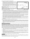
4. Test for spillage at the burner inlet air location around the VRV after 5 minutes of operation. Use a draft gauge, flame of a match or
candle, or smoke from a cigarette, cigar or pipe. Shut off appliance thermostat and check for spillage around the VRV. If a flow
reversal is noticed, house depressurization is occurring and make up air is required.
MAINTENANCE
Inspect all vent connections annually for looseness, evidence of corrosion, or flue gas leakage. Replace, seal, or tighten pipe
connections if necessary.
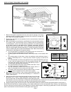
As part of the yearly maintenance schedule, remove the Intake Access Panel on the exterior of the FDVS vent termination (See Figure
2) and remove any debris or foreign material. Be sure to properly replace the panel.
Figure 3 – Top View