


Page 4
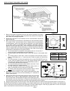
Figure 4
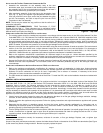
Figure 5
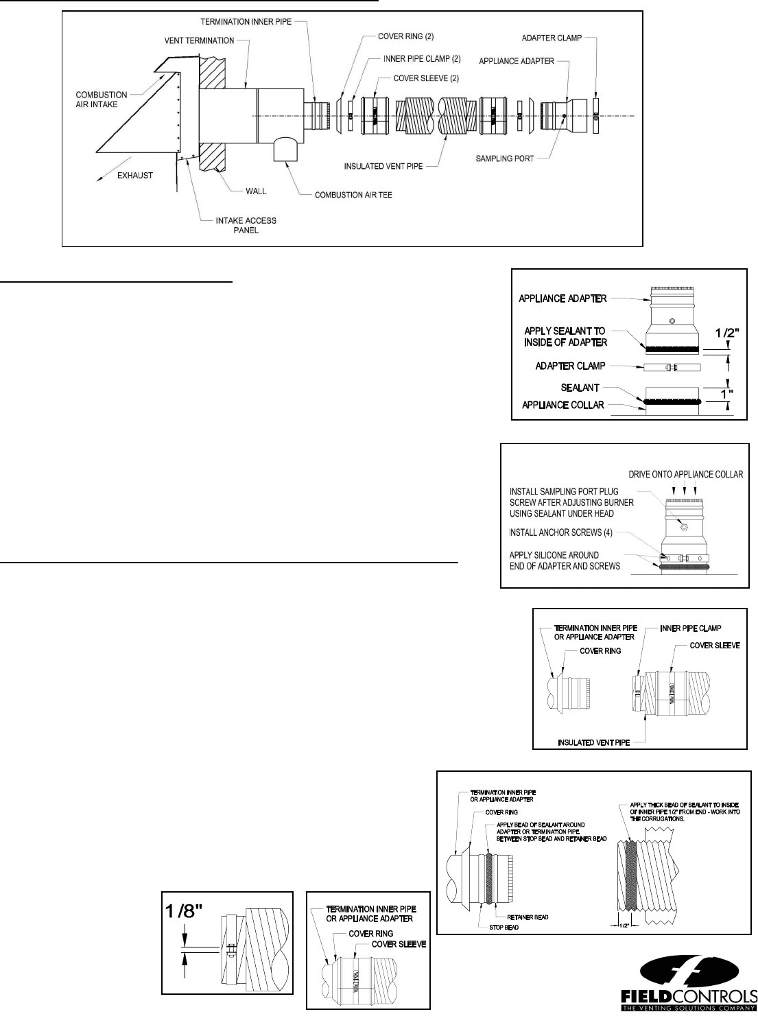
FIELD CONTROLS DIRECT VENT SYSTEMS VENT PIPE ASSEMBL
Y
APPLIANCE ADAPTER INSTALLATION:
1. Apply a bead of sealant to appliance collar approx. 1” from end of collar (Figure 5).
2. Remove all oil and grease from the inside of the appliance adapter, and apply a bead
of sealant to inside of adapter ½” from end (Figure 5).
3. With a twisting motion, assemble the appliance adapter onto the appliance collar.
4. Using a mallet and block of wood, drive the adapter onto the appliance collar, using
care to avoid damaging the appliance collar or the adapter (Figure 6).
5. Assemble adapter clamp halves using the supplied 5/16” bolts and square nuts, and
install the appliance clamp onto the adapter and tighten securely (Figure 5).
6. Install the supplied self-drilling, self-tapping anchoring screws through the 4 holes in
the appliance clamp into the appliance collar (Figure 6). No pilot hole is required.
7. Apply sealant to the end of the adapter and anchoring screws. (Figure 6).
8. After testing and burner adjustments have been made, apply sealant to the supplied
3/8” sampling port plug screw and install the screw in the sampling port (Figure 6).
9. Maintain the appliance manufacturer's clearances to combustibles. If the appliance
collar is within 18" of combustible material, wrap minimum 1-1/2" ceramic insulation
(installer-supplied) around the exposed portion of the termination inner pipe and
appliance adapter (Figure 10).
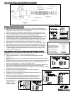
JOINT ASSEMBLY: VENT PIPE TO TERMINATION AND APPLIANCE ADAPTER
If necessary, the vent pipe may be cut to length with a hacksaw or cut off saw.
CAUTION: Use safety glasses and other appropriate safety gear.
1. Pull outer vent pipe back 1”-2” from inner vent pipe end and remove insulation
(Figure 7).
2. Slide Cover Sleeve onto end of vent pipe a few inches back from end of outer vent pipe
(Figure 7).
3. Slide Cover Ring over stop bead on termination inner pipe or appliance adapter (Figure 7).
4. Assemble inner pipe clamp halves using the supplied ¼” bolts and square nuts, and
position inner pipe clamp ¼” from end of inner pipe (Figure 7).
5. Remove all oil and grease from end of termination inner pipe or appliance adapter, and
apply a bead of sealant to between the stop bead and retainer bead (Figure 8).
6. Apply a thick bead of sealant to inside of inner vent pipe ½” from the end of pipe, working
the sealant into the corrugations (Figure 8).
7. Push the inner vent pipe onto the termination inner pipe or appliance
adapter all the way up to the stop bead.
8. Tighten the inner pipe clamp bolts until both clamp halves are within 1/8”
of each other at each end (Figure 9).
9. Slide the cover sleeve and cover ring together to engage the ring in the
groove of the sleeve, and tighten the cover sleeve clamp (Figure 10).
10. To maintain 1" clearance to combustibles, wrap minimum 1-1/2" thick
ceramic insulation (installer-supplied) around the exposed portion of the
termination inner pipe
(Figure 10), and
secure with foil tape
(installer supplied).
P/N 46483500 Rev B 09/05
Figure 7
Figure 8
Figure 9
Fi
g
ure 10
Figure 6