


Page 4
INSTALLATION SAFETY INSTRUCTIONS
CAUTION: This device must be installed by a qualified installer in accordance with the manufacturer's installation
instructions. Appliances should have a minimum of 75% combustion efficiency or have a maximum measured flue gas
temperature of 550°F at the inlet of the venter.
1. The power venting system must be installed by a qualified installer. "Qualified Installer" shall mean an individual who
has been properly trained or a licensed installer. The installer must write or imprint his name, phone number and date
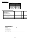
of installation on the installation tag. The tag should be attached to the power venter unit. Recording burner and
venting system initial operational information is recommended as a guide for service or burner tune-up. Enter this on
the back page of this manual.
2. Safety inspection of a venting system should be performed before and after installing a power venting system on an
existing or new appliance. Procedures to follow are those recommended by the National Fuel Gas Code,
A.N.S.I.Z223.1 or refer to the "General Installation Inspection" section of this manual.
3. Plan the vent system layout before installation to avoid the possibility of accidental contact with concealed wiring or
plumbing inside walls.
4. Single wall vent pipe may be used to join an appliance to the venting system, but if proper clearances cannot be
maintained from combustible materials, Class B Vent Pipe should be used for gas appliances. Refer to national or
local codes for guidelines.
5. Disconnect power supply before making wiring connections to prevent electrical shock and equipment damage.
6. This equipment is designed to overcome minor negative pressure conditions. To ensure extreme negative pressure
does not exist, follow the "General Installation Inspection" section of this manual.
7. Heating appliances equipped with draft hoods, such as boilers or furnaces, LP and natural gas appliances SHOULD
have a secondary spillage switch installed. On appliances without draft hoods, it is recommended that the secondary
safety switch GSK-3 be installed into the system. Gas-fired 30 millivolt power systems MUST be equipped with a
spillage switch.
8. Air flow adjustment MUST be made to ensure appliance efficiency. This should be done at the appliance exhaust
outlet with a velocity meter, draft gauge or by the "match test procedure". The match test is in accordance with
National Fuel Gas Code A.N.S.I.Z223.1, Section 8.6.
9. On heating appliances not equipped with a draft hood, a barometric draft control MUST be installed to regulate proper
air flow and fluctuations in the system's air flow during operation. Fluctuations can come from wind loads on the outlet
of the venter, house depressurization during windy days and the different house ventilation requirements between
summer and winter operation. Use a Field Controls Type MG-1 Barometric Draft Control. Gas-fired draft induced
systems should have a single-acting or double-acting barometric draft control installed.
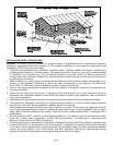
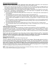
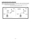
Diagram A