


Page 5
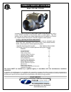
INSTALLATION OF POWER VENTER
CAUTION: Failure to install, maintain and/or operate the power venting system in accordance with manufacturer's
instructions will result in conditions which may produce bodily injury and/or property damage.
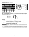
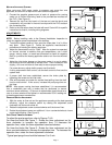
1. Remove power venter from box and inspect unit for damage. If the carton has been crushed or mutilated, check unit
very carefully for damage. Rotate venter wheel to insure that the motor and venter wheel rotate freely. DO NOT install
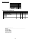
if any damage is apparent. Refer to unit sizing chart to check proper venting sizing.
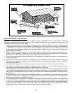
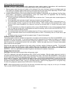
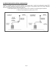
2. Location of the termination of the venting system should be installed in accordance with the National Fuel Gas Code,
A.N.S.I.Z233.1, manufacturer's recommendations, and/or local codes which are applicable. See the following
requirements or refer to Diagram A for typical locations.
a. The exit termination of mechanical draft systems shall not be less than 7' above grade when located adjacent to
public walkways.
b. A venting system shall terminate at least 3' above any forced air inlet located within 10'.
c. The venting system of other than a direct vent appliance shall terminate at least 4' below, 4' horizontally from, or 1'
above any door, window, or gravity air inlet into the building. When venting oil fired equipment with a Field
Control’s CAS-2 series Airboot® kit, the intake air hood can be mounted within 12 inches of the power venter
exhaust.
d. The vent termination of a direct vent appliance with an input of 50,000 BTU/Hr or less, shall be located at least 9"
from any opening through which vented gases could enter the building. With an input over 50,000 BTU/Hr, a 12"
termination clearance shall be required.
e. The vent termination point shall not be installed closer than 3' from an inside corner of an L-shaped structure.
f. The vent termination should not be mounted directly above or within 3' horizontally from an oil tank vent or gas
meter.
g. The bottom of the vent terminal shall be located at least 12" above finished grade.
C
ONNECTING VENTER TO APPLIANCE
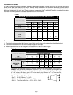
The venting system should be installed and supported in accordance with the National Fuel Gas Code ANSIZ223.1, or in
accordance with any local codes. A vent pipe connector shall be supported for the design and weight of the material
employed, to maintain clearances, prevent physical damage and separation of joints. A vent pipe increaser or reducer
may be required for connecting the venter to the vent system. Smaller vent pipe sizes than a chimney-vented system
may be used for the vent system.
Route the vent pipe from the appliance to the venter using a minimum number of elbows as possible. The horizontal
section of the vent pipe should have a slight upward slope from the appliance to the venter. For clearances to
combustible materials, multiple appliance venting and other installation requirements, refer to the National Fuel Gas Code
ANSIZ223.1, and/or any applicable local codes or appliance manufacturer’s installation instructions.
G
ENERAL WIRING INSTRUCTIONS
CAUTION: Disconnect electrical power before wiring power venter!
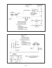
The PVO is designed to be used with appliances with 120VAC control systems. Wire the venter motor and controls in
accordance with the National Electric Code, and/or applicable local codes. UNIT MUST BE GROUNDED. Check ground
circuit to make certain that the unit has been properly grounded. The wiring should be protected by an over-current circuit
device rated at 15 amperes. CAUTION MUST be taken to ensure that the wiring does not come in contact with any heat
source. All line voltage and safety control circuits, between the venter and appliance, MUST be wired in accordance with
the National Electrical Code for Class 1 wiring, or equivalent methods. Refer to wiring diagrams B & C for typical wiring.
For other wiring diagrams, please contact Field Control’s Technical Support.
NOTE: When applying power to the PVO for the first time, the venter motor may, or may not, run for up to 10 minutes.
This is normal, and will not affect the operation of the system.