


3
This product should not be sealed into the bench with silicone or glue. Doing so will make future
servicing difficult. Fisher & Paykel will not be liable for costs associated with releasing such a
product, nor for repairing damage that may be incurred in doing this.
When this product is installed it shall not be used as a space heater, especially if installed in
marine craft or caravans.
No combustible material or products should be placed on this product at any time.
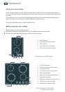
Before you install the appliance, ensure that
the benchtop is square and level and no structural members interfere with space requirements.
there is a minimum of 60 mm between the cutout and the rear or side wall.
if the cutout is less than 100 mm from the wall, some form of protection against heat is used, such
as ceramic tiles.
if the appliance is a CT2802 model, the power supply cable is rated for use at 100
O
C.
a suitable disconnection switch is incorporated in the permanent wiring, mounted and positioned
to comply with local wiring rules and regulations. A means of disconnection with at least a 3 mm
air gap contact separation in all poles must be incorporated into the fixed wiring in accordance
with the wiring rules, unless the local wiring rules allow for the following variation of these
requirements: A means of disconnection from the supply having an air gap separation in all
active (phase) conductors must be incorporated into the fixed wiring.
the interconnection cord between the cooktop and the oven or control box will not be accessible
via cupboard doors after installation. This applies to any extension cord as well, even if they are
double-insulated.
you consult local building authorities and by-laws if in doubt regarding installation.
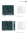
the appliance is rated 5.9 kW at 220-240 V (CT560C,CT5602F,CT6551S models) or 3.0 kW at
220-240V (CT2802 models).
When you install the appliance, ensure that you comply with the following requirements:
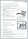
If prolonged use is anticipated, or the cooktop is mounted above a drawer space, a thermal
protection barrier between is recommended AND
Where the base of this product is accessible after installation, a thermal protection barrier MUST
be installed to prevent contact.
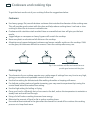
If a thermal protection barrier is installed below the cooktop, this barrier must be made of heat
resistant material capable of withstanding sustained exposure to temperatures up to 70
o
C,
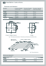
be at least 30 mm and no greater than 75 mm below the base of the cooktop and have FOUR
ventilation holes or TWO similiar holes for CT2802 models (min 50 mm – max 70 mm diameter,
see Fig. 1 for details). These ventilation holes must be open to free air.
We recommend that the thermal protection barrier be removable, so that the cooktop can be
easily secured with the supplied clamps.
Use easy-to-clean finishes for the wall surfaces surrounding the cooktop, so that cooking fume
staining resulting from using the cooktop is easy to remove.
Safety and warnings