


14
3 TECHNICAL OVERVIEW
3.1 Chassis
The DishDrawer™ chassis is one complete assembly composed of 5 steel metal components locked together by a
proprietary riveting process. The chassis exterior is made of a lacquered electro-galvanised material.
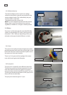
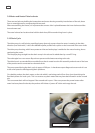
3.2 Drawer Fronts
Prenished drawer fronts are formed from steel blanks. The drawer fronts are attached to the tub by means of
formed hooks and two pins that are inserted through either side of the tub.
On the integrated model, the front panel supplied on each drawer is the mounting panel for the joinery
nished drawer front. The joinery nished drawer front is supplied by the customer.
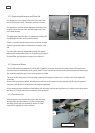
3.3 Electronics
In the electronic controller, the functions of controlling the motor as well as controlling the user interface
console are combined into a single micro controller on the main printed circuit board.
This micro controller also controls a transformerless 85w switch mode power supply. This power supply
utilises a large dropping resistor on the heater plate in conjunction with phase control of the mains voltage in
order to produce a variable voltage supply for the motors, solenoids and drying fan. From this the controller can
supply voltages from 16V to 85V to the various components in the DishDrawer™.
A separate 24volt dc power supply on the PCB mains lter board, (located within the mains lter housing in the
lower left corner of the chassis) supplies power to the electronic controller(s). A switch mode power
supply on the electronic controller converts this to 5V which powers the microcontroller and LED’s.
An isolation relay is mounted on the PCB mains lter and will disconnect power to major components when
signalled to by the controller under certain fault conditions. Once the fault has been cleared, it will require the
power to be disconnected from the product for the isolation relay to reset.
NOTE: - With power supplies of this nature, all components, regardless of supply voltage, should be treated as live
to earth. i.e. at supply voltage.
The user interface comprises a printed circuit board for front controls and a touch switch panel for internal
controls.
The element is switched by one single pole relay. Overheat protection is provided by a thermal fuse in series with
the water heater track on the heater plate. In an over-heat situation, this gravity fuse drops o and disconnects
the water heater element from the supply voltage.
A non-serviceable fuse is mounted within the controller to provide additional safety protection.
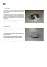
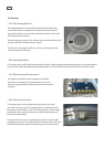
3.3.1 Tub Home Sensor
The tub home sensor determines when the tub is closed. The tub home sensor consists of an infrared transmitter
and receiver mounted on the right side of electronic controller. When the tub is fully closed, infrared light is
transmitted from the sender through a light pipe on the side of the tub, through a prism mounted in the chassis
trim, then back through the other light pipe to the receiver. If the tub is not fully closed, the circuit is not
complete and the appliance will not operate.