


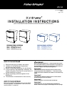
PLEASE NOTE: Your model of DishDrawer® may differ from the model shown in the installation
diagrams. Installation is similar for all models for either Single or Double models.
Information referring
to Single models only is highlighted in blue.
Installation diagrams have been simplified to enable
clearer instruction. FOR INTEGRATED PRODUCTS FOLLOW THE INTEGRATED PANEL PREPARATION
INSTRUCTIONS P/N 526608, BEFORE MOVING THE PRODUCT INTO THE CAVITY.
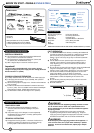
R
READ THESE INSTRUCTIONS
COMPLETELY AND CAREFULLY.
Important!
DO NOT push
middle of drawer(s).
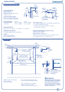
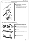
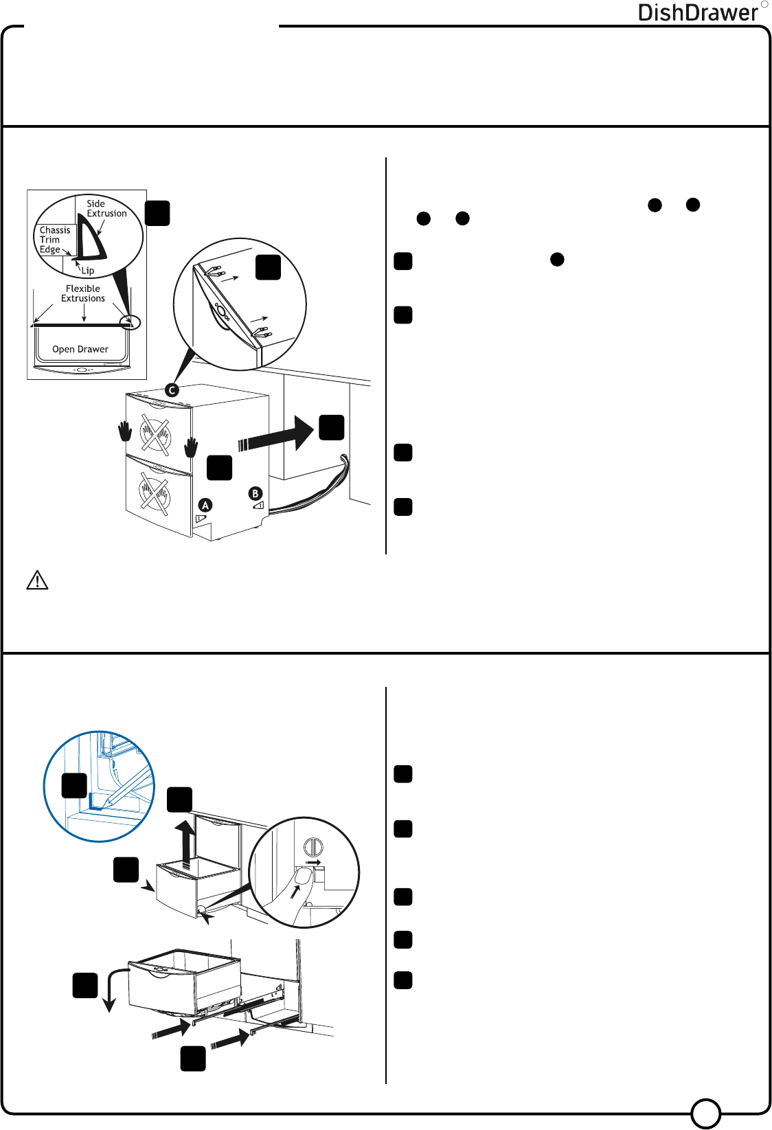
MOUNTING TAB OPTIONS
The mounting tabs are in pairs, one on each side of the product. They are
used to secure the product to the cavity sides. Installation requires two
sets of tab pairs be used. DOUBLE MODELS ONLY -
A and B tab pairs
OR
B and C tab pairs may be used. All tabs would be optimum.
If the top installation tabs
C are to be used, fit to the chassis by
inserting into the top slots as shown. Ensure the tabs are fully
locked in place.
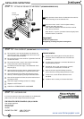
Optional Flexible Extrusion
If the cavity is 24” x 34
1
/
2
” (610mm x 876mm) flexible extrusions
can be attached along the top and sides of the product. Open the
drawer(s) to expose the chassis trim. Remove extrusion backing
and adhere to the side and top of DishDrawer®. Refer to the
drawing for correct placement.
Be sure that extrusions do not prevent the drawer from closing
completely.
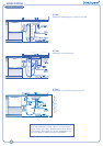
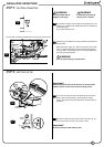
Check cavity for any obstructions that may interfere with sliding
the product back. DOUBLE MODELS ONLY - loosen the feet first.
Push product into cavity to suit adjacent cabinetry. Do not push
middle of drawer(s). Be sure inlet, drain hose(s) and power supply
cord are not restricted or damaged by carefully pulling all excess
length through the services hole, while the product is being pushed
back into the cavity.
FOR SINGLE MODELS, check that the base of the product is not
bowed. Do not rest single models on your knee when moving them
into the cavity.
1
2
3
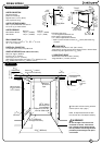
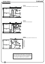
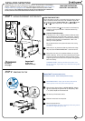
Important!
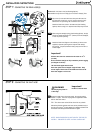
(SINGLE MODELS ONLY).
The product may move. Mark chassis position on cavity.
SINGLE MODELS ONLY. Gently open the drawer and mark the
chassis position on the cavity, before removing the tub.
Open the drawer (bottom drawer in DOUBLE MODELS). Release
the tub by depressing the right hand tub clip and pushing it back
1
3
/
16
” (30mm). Repeat on the left hand side.
Lift the tub up off the drawer runners.
Slide both runners back into the product.
Place the tub onto the floor.
For SINGLE MODELS, depending on the height of the cavity, the tub
will need to be supported, eg on a chair.
6
7
1
3
2
5
9
7
6
8
9
8
INSTALLATION INSTRUCTIONS
STEP 1: MOVING THE PRODUCT INTO THE CAVITY
WARNING!
Be careful of
sharp edges.
STEP 2: REMOVING THE TUB
5
7
4
4