


7
Installation instructions
11
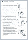
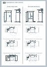
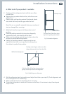
Attach double sided foam to the back of the water filter head as shown in
Diagram 5. Write the date to be replaced on the filter (date installed + 6
months). Remove double sided foam backing and attach filter to the desired
position as located in step 10 (refer to previous page).
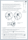
12
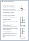
Run the 6 mm (¼”) tubing to back of the fridge ensuring there is enough
tubing to pull out the refrigerator for service.
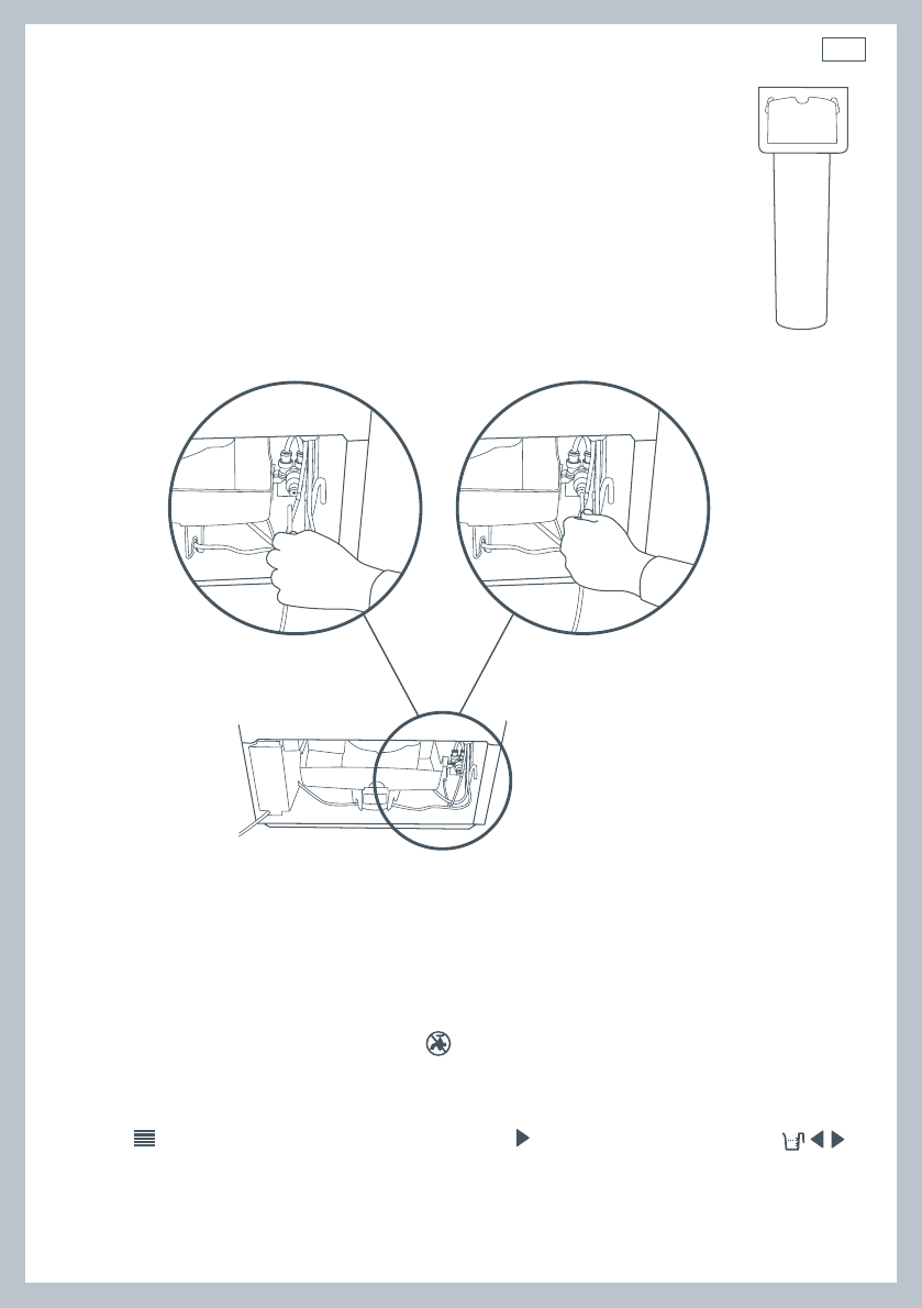
13
Connect tubing into the water (solenoid) valve located on the right hand side of
the unit (compressor) compartment as shown in Diagram 7. Beware of hot pipes.
14
Pull gently on tubing to ensure it is locked in as shown in Diagram 8.
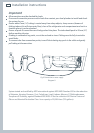
15
The completed installation should look like Diagram 9 on page 8.
Fig.8 Waterline connection
to refrigerator
Diagram 7
Diagram 6
Diagram 8
16
Turn isolating tap on and check that all connections are dry and free of drips. If not, please alert
the plumber.
17
Coil water line tubing behind the fridge. Push your refrigerator into place being careful not to
kink or squash the water line running into the water (solenoid) valve.
18
Read pages 9 – 14 carefully, and then turn refrigerator on.
19
The first time you require water out of the dispenser, there will be a delay while the water
reservoir fills up. As this is happening, the symbol will flash. Once the reservoir is full, this
symbol will stop flashing.
20
Run a further 3 litres (3 qt) through the system, stopping intermittently to ensure the reservoir is
flushed out. Failure to do this will result in excessive dripping from your dispenser.
21
Press until the Ice menu is highlighted then press to turn on the ice maker. Press
together to force a cycle. The ice tray will flip. Force another cycle. The ice tray will flip and spill
the water into the ice bin. Empty water and replace bin.
22
You are now ready to enjoy chilled water and ice dispensing from your Active Smart™ refrigerator.
Please note that once installation is complete a few drips may appear out of the dispenser over
the next few days as the remaining trapped air is cleared.
Diagram 5
Fig.7 Double sided
foam attachment