


11
OAC: AUX output configuration: (AL, Li, UL, Ip, AA, rE, dF, C2)
AL: alarm output; Li: light of the cabinet; UL: for the ultra-violet light (It is actionable only when the controller is
in OFF position); Ip: to extract the insert probe (It is actionable only when the controller is in OFF position); AA:
anti - condensation; rE: the IV relay works as a thermostat, with direct action (cooling) (OAH>0), and inverse
actions (heating) (OAH<0); dF: the IV relay is activated during the defrost, at the end of the defrost it remains
ON for the OAt time; C2: second compressor. See 1c2 parameter for different settings.
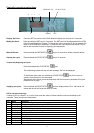
OAP AUX output polarity (OP ÷ CL) OP= normally open; if it is ON the terminals 6-8 are closed. CL= normally
closed; if it is ON the terminals 6-7 are closed.
OAt AUX output timer: (0÷255 min) time in which the AUX output stays ON. It is enabled when OAC = Li or
UL or Ip or AA or dF.
OAS Set point for AUX output (-50÷50; ris.1 °C/ 1°F)
OAH Differential for AUX output: (-12.0÷12,0; ris.0,1°C/1°F, always ≠0) Intervention differential for the set point
of the auxiliary, with OAH<0 the action is for heating, with OAH>0 it is for cooling. COOLING: AUX cut IN is
OAS Plus Differential (OAH>0). AUX cut OUT is when the temperature reaches the set point OAS.
HEATING: AUX cut IN is OAS Plus Differential (OAH<0). AUX cut OUT is when the temperature reaches the set
point OAS.
OAi Probe selection for the AUX output (rP, EP, iP) rP = thermostat probe, EP = evaporator probe; iP =
insert probe
DEFROST
tdF Defrost type (not present in the XB350C): (rE= electrical heater; in = hot gas).
dPO Defrost before the holding: no= no defrost; YES= defrost at the start of a holding cycle.
IdF Interval between defrost cycles: (0.1÷ 24.0; res. 10 min) Determines the time interval between the
beginning of two defrost cycles. (with 0.0 the defrost is disabled)
dtE Defrost termination temperature (not present in the XB350C): (-50÷50 °C/°F) Sets the temperature
measured by the evaporator probe, which terminates the defrost.
MdF Maximum length for defrost: (0÷255 min) When EPP = no (timed defrost) it sets the defrost duration, when
EPP = YES (defrost termination based on temperature) it sets the maximum length for defrost.
dFd Temperature displayed during defrost: (rt , it, SEt, dEF) rt: real temperature; it: temperature at the start
of defrost; SEt: set point; dEF: “dEF” message
Fdt Drip time (not present in the XB350C): (0 ÷ 60 min) Time interval between reaching defrost termination
temperature and the restoring of the controllers' normal operation. This time allows the evaporator to eliminate
water drops that might have formed during defrost.
FANS
FnC Fans operating mode during the holding phase:
C-n= runs with the compressor, OFF during defrost; o-n = continuous mode, OFF during defrost; C-Y = runs
with the compressor, ON during defrost; o-Y = continuous mode, ON during defrost;
FSt Fan stop temperature: (-50÷50°C/°F; res. 1°C/1°F) if the temperature, detected by the evaporator probe is
above FSt fans are stopped. It serves to avoid blowing warm air around the room.
AFH Differential for the stop temperature and for the alarm (0.1 ÷ 25.0 °C; ris.0.1°C/1°F) Fans carry on working
when the temperature reaches the FSt-AFH value, the temperature alarm recovers when the temperature is
AFH degrees below the alarm set.
Fnd Fan delay after defrost: (0 ÷ 255 min) The time interval between end of defrost and evaporator fans start.
ALARM
ALU MAXIMUM temperature alarm: (1 ÷ 50 °C/°F) When the “SET+ALU” temperature is reached the alarm is
enabled, (possibly after the “Ald” delay time).
ALL Minimum temperature alarm: (1÷50°C/1°F) When the “SET-ALL” temperature is reached the alarm is
enabled, (possibly after the “Ald” delay time).
ALd Temperature alarm delay: (0÷255 min) time interval between the detection of an alarm condition and alarm
signalling.
EdA Temperature alarm delay at the end of defrost: (0 ÷ 255 min) Time interval between the detection of the
temperature alarm condition at the end of defrost and alarm signalling.
tbA Silencing alarm relay: (Yes= silencing buzzer and alarm relay, no= only buzzer silencing).
OTHER
Ad1 Address 1 for RS485: (0 ÷ 94)
Ad2 Address 2 for RS485 (0 ÷ 94)
Lod: Local display: (rP, EP, iP, nr) Select which probe is displayed by the instrument. rP: Thermostat probe.
EP: Evaporator probe. iP: Insert probe, nr: During a temperature cycle the insert probe is displayed, during the
holding phase the room probe is displayed. If the cycle is made by time the time remaining is displayed (in
minutes).
rEd Remote display: (rP, EP, Ip) select which probe is displayed by the XR REP. rP: thermostat probe; EP:
evaporator probe; iP: insert probe.
Loc Set point of the holding phase lock (no - YES) It locks the set point of the holding phase.