


6
30" ELECTRIC SLIDE-IN RANGE INSTALLATION INSTRUCTIONS
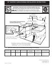
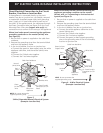
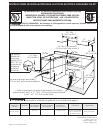
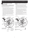
Four Conductor Wire Connection to Range
Where local codes does NOT permit connection of the
frame grounding conductor to the neutral wire of the
copper power supply cord (see Figure 4):
1. Remove the 3 screws at the lower end of the rear
wire cover, then raise the lower end of the rear
wire cover (access cover) upward to expose range
terminal connection block (see figure 2).
2. Remove the grounding strap from the terminal block
and from the appliance frame.
3. Using the nuts supplied with the literature package,
connect the ground wire (green) of the copper
power supply cord to the frame of the appliance
with the ground screw, using the hole in the frame
where the ground strap was removed (see Figure 4).
4. Connect the neutral of the copper power supply
cord to the center silver-colored terminal of the
terminal block, and connect the other wires to the
outer terminals. Match wires and terminals by color
(red wires connected to the right terminal, black
wires connected to the left terminal).
5. Lower the terminal cover and replace the 3 screws.
Terminal Block Silver Colored Terminal
Red
Wire
Neutral
(White Wire)
Ground (Bare
Copper Wire)
To 240 V Receptacle
A User Supplied
Strain-relief Must
Be Installed at This
Location
Black Wire
1 1/8" (2.9cm)
Dia. Direct
Connection
Hole. Punch
Out Knockout
for 1 3/8"
(3.5cm) Dia.
Cord Kit Hole.
NOTE: Be sure to remove the
supplied grounding strap.
Figure 4
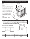
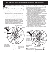
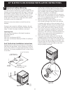
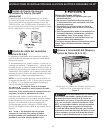
4. Electrical Connection to the Range
(U.S.A.)
Three Conductor Wire Connection to Range
If local codes permit connection of the frame grounding
conductor to the neutral wire of the copper power
supply cord (see Figure 3):
1. Remove the 3 screws at the lower end of the rear
wire cover, then bend the lower end of the rear
wire cover (access cover) upward to expose range
terminal connection block (see Figure 2).
2. Using the nuts supplied in the literature package,
connect the neutral of the copper power supply cord
to the center silver-colored terminal of the terminal
block, and connect the other wires to the outer
terminals. Match wires and terminals by color (red
wires connected to the right terminal, black wires
connected to the left terminal) (see figure 3).
3. Lower the terminal cover and replace the 3 screws.
Figure 3
Silver Colored Terminal
1 1/8" (2.9 cm) Dia.
Direct Connection
Hole. Punch Out
Knockout for 1 3/8"
(3.5 cm) Dia. Cord
Kit Hole.
To 240 V
Receptacle
A User Supplied
Strain-relief Must
Be Installed at This
Location.
Black
Wire
Terminal
Block
Cord
Mounting
Plate
Neutral
(White Wire)
Grounding
Strap
Red Wire