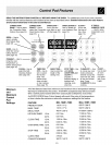
Control Locations of the Gas Surface
Burners
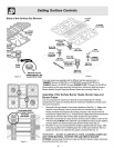
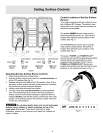
Your range is equipped with gas surface burners
with 4 different BTU ratings. The ability to heat
food quicker and in larger volumes increases as
the burner size increases.
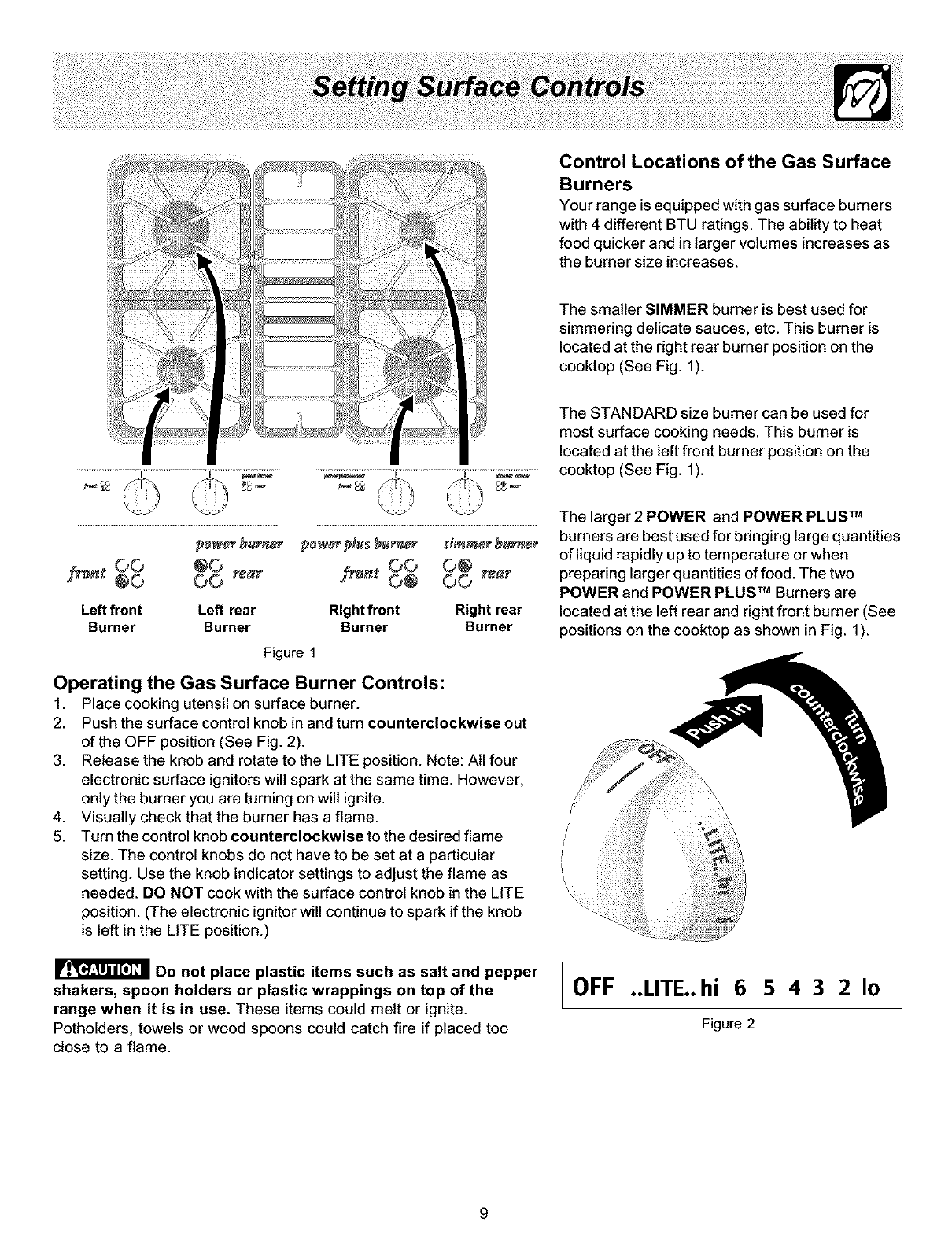
The smaller SIMMER burner is best used for
simmering delicate sauces, etc. This burner is
located at the right rear burner position on the
cooktop (See Fig. 1).
The STANDARD size burner can be used for
most surface cooking needs. This burner is
located at the left front burner position on the
cooktop (See Fig. 1).
Sron_O0 @0
®0 O0 rear
Left front Left rear Right front
Burner Burner Burner
power p_u_burner _imm_r burn¢_
fi_nt, O0 O®
Q@ OO rear
Right rear
Burner
Figure 1
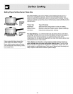
Operating the Gas Surface Burner Controls:
1. Place cooking utensil on surface burner.
2. Push the surface control knob in and turn counterclockwise out
of the OFF position (See Fig. 2).
3. Release the knob and rotate to the LITE position. Note: All four
electronic surface ignitors will spark at the same time. However,
only the burner you are turning on will ignite.
4. Visually check that the burner has a flame.
5. Turn the control knob counterclockwise to the desired flame
size. The control knobs do not have to be set at a particular
setting. Use the knob indicator settings to adjust the flame as
needed. DO NOT cook with the surface control knob in the LITE
position. (The electronic ignitor will continue to spark if the knob
is left in the LITE position.)
Do not place plastic items such as salt and pepper
shakers, spoon holders or plastic wrappings on top of the
range when it is in use. These items could melt or ignite.
Potholders, towels or wood spoons could catch fire if placed too
close to a flame.
The larger 2 POWER and POWER PLUS TM
burners are best used for bringing large quantities
of liquid rapidly up to temperature or when
preparing larger quantities of food. The two
POWER and POWER PLUS TM Burners are
located at the left rear and right front burner (See
_ositions on the cooktop as shown in Fig. 1).
OFF ..LITE..hi 6 5 4 3 2 I0
Figure 2
9


