6
Fastening the hood to the wall cabinetFastening the hood to the wall cabinet
Fastening the hood to the wall cabinetFastening the hood to the wall cabinet
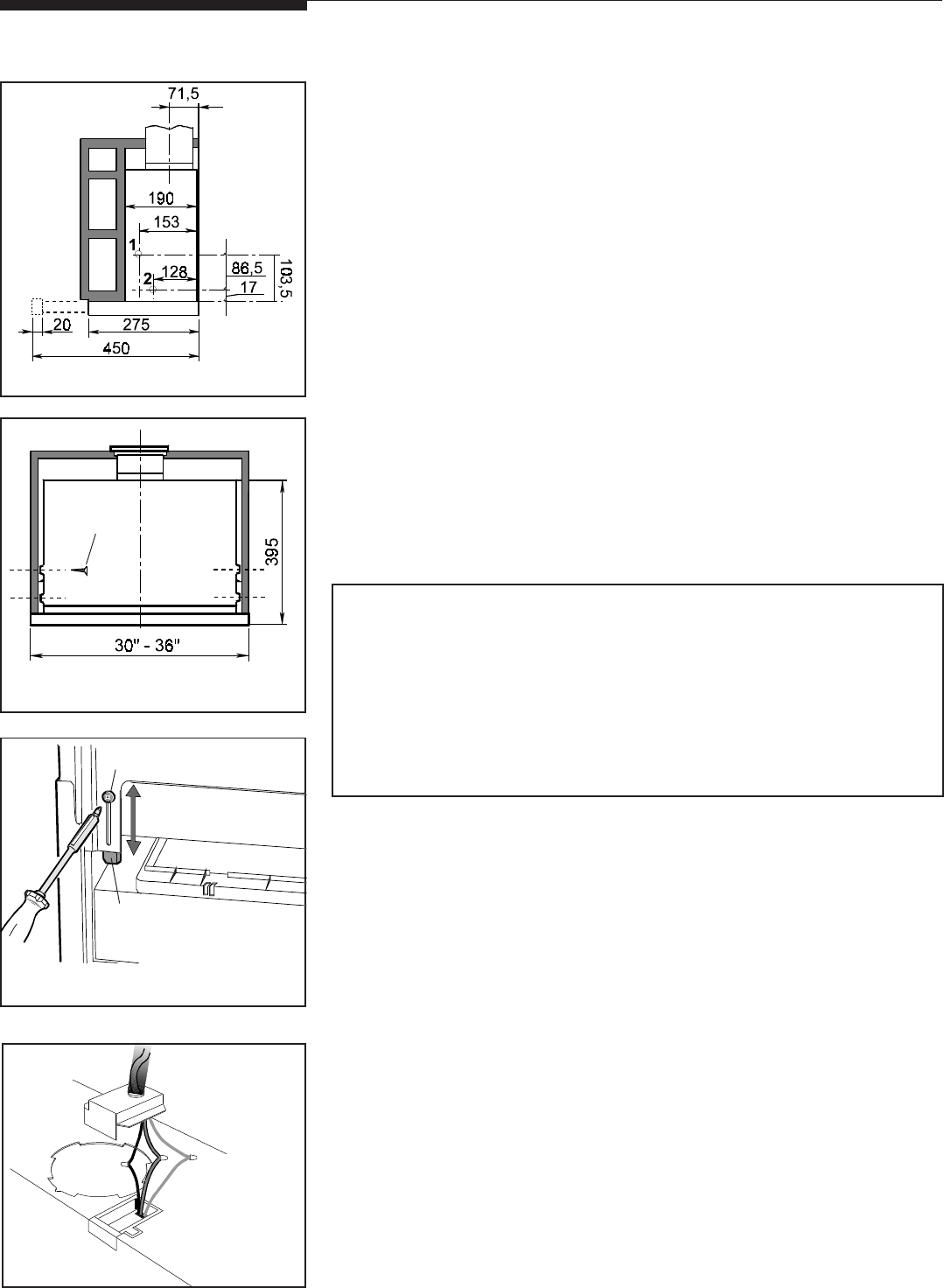
Fastening the hood to the wall cabinet
Fit the drilling template, which comes with the hood, on the inner right side
of the cabinet making sure side “A” coincides with back part.
Make at least two 2 mm. diameter holes at points 1-2 (Figure 5).
Perform the same operations on the inner left side.
Use screws
FF
FF
F (4.5x16) to fasten the hood to the cabinet (Figure 6).
Attention! Attention!
Attention! Attention!
Attention! While mounting the hood on the wall cabinet be sure once the
hood has been fastened, to allow the wiring compartment to be easily and
safely reachable, in order to make eventual safety inspections and/or
maintenance operations.
Box adjustmentBox adjustment
Box adjustmentBox adjustment
Box adjustment
The hood can be installed in cabinets with different depths; the front of the
box must always be in line with the cabinet.
For alignment, adjust the back stops of the box.
For box adjustment, loosen screws
MM
MM
M, slide the square plates
PP
PP
P as necessary,
and tighten screws
M M
M M
M (Figure 7).
Ensure that the drawer, when fully retracted, turns OFF all power by acting
positively on the rear microswitch.
Wiring to Power SupplyWiring to Power Supply
Wiring to Power SupplyWiring to Power Supply
Wiring to Power Supply
WARNING!WARNING!
WARNING!WARNING!
WARNING!
ELECTRICAL GROUNDING INSTRUCTIONSELECTRICAL GROUNDING INSTRUCTIONS
ELECTRICAL GROUNDING INSTRUCTIONSELECTRICAL GROUNDING INSTRUCTIONS
ELECTRICAL GROUNDING INSTRUCTIONS
THIS APPLIANCE IS FITTED WITH AN ELECTRICAL JUNCTION BOX WITH
3 WIRES, ONE OF WHICH (GREEN/YELLOW) SERVES TO GROUND THE
APPLIANCE. TO PROTECT YOU AGAINST ELECTRIC SHOCK, THE GREEN
AND YELLOW WIRE MUST BE CONNECTED TO THE GROUNDING WIRE
IN YOUR
HOME ELECTRICAL SYSTEM, AND IT MUST UNDER NO CIRCUMSTANCES
BE CUT OR REMOVED.
Warning: Turn off power circuit at the service panel before wiring this unit.
120 VAC, 15 or 20 Amp circuit required.
a.a.
a.a.
a. Remove j-box cover as shown in Figure 8.
b.b.
b.b.
b. Remove the knockout and install the strain relief (conduit) connector (1/
2") in junction box.
c.c.
c.c.
c. Run 3 wires; black, white and green (#16 AWG) in 1/2" conduit from
service panel to junction box.
d.d.
d.d.
d. Connect black wire from service panel to black or red in junction box,
white to white and green to green-yellow. See Figure 8.
e.e.
e.e.
e. Close junction box cover, check all light bulbs to make sure they are
secure in their sockets, then turn power on in service panel and check
lights and blower operation per Care & Use section of this manual and
install filters.
f.f.
f.f.
f. Make sure to leave this manual for the home owner.
InstallationInstallation
InstallationInstallation
Installation
Figure 5Figure 5
Figure 5Figure 5
Figure 5
Figure 6Figure 6
Figure 6Figure 6
Figure 6
Figure 7Figure 7
Figure 7Figure 7
Figure 7
FF
FF
F
MM
MM
M
PP
PP
P
Figure 8Figure 8
Figure 8Figure 8
Figure 8


