


2-11
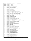
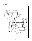
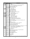
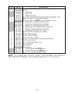
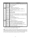
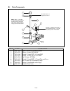
ITEM PART # COMPONENT
1 900-7532 Box, Control
2 807-1396 Relay, 24VDC SPDT (Basket Lift Relay – GSMS and GBC units only)
3 810-0045 Bushing, .875 Diameter Hole
4 807-0067 Block, 8-Pin Terminal
5 807-0255 Strip, Terminal
6 Transformer
807-0800 120VAC/24VAC, 50/60 Hz, 50VA
807-0680 208-240VAC/24VAC, 50/60 Hz, 43VA
7 807-3366
Module, Honeywell Dual-Spark FV Ignition (See NOTE below.)
8 807-0670 Relay, 24V DPDT (Heat Relay – all units)
9 900-1924 Guard, Finger
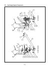
10 826-1371 Screw, #8 x ½-inch Drill Point Hex Head Zinc Plated (Pkg. of 25)
11 807-1713 Sound Device (Alarm)
12 807-1292 Fitting, Plastic Conduit
13 807-1319 Connector, 90° #5252
14† 812-1193 Conduit, ½-inch x 53-inch Flexible Plastic (cut to length from 811-0808)
15† 812-1187 Conduit, ½-inch x 18-inch Flexible Plastic (cut to length from 811-0808)
16† 812-1192 Conduit, ½-inch x 47-inch Flexible Plastic (cut to length from 811-0808)
17 809-0290 Clamp, Cable
18 807-0170 Box, Electrical Handy
19 807-1612 Clamp, ⅜-inch Twin-Screw Connector
20 900-8016 Cover, Electrical Handy Box
21 826-1363 Screw, 8-32 x ½-inch Slotted Truss Head Nickel Plated (Pkg. of 25)
22 Cordset
807-0154 120VAC (illustrated)
807-1685 208-240VAC (not illustrated)
23 106-0676SP Cable, Ignition (used with Item 7 – also requires Item 28)
24 807-1709 Cable, Ignition (used with 807-1006 Ignition Modules)
25 806-5316SP Wire Assembly, 20-inch High Temperature (Flame Sensor Wire)
26 809-0362 Screw, #8 x 1¼-inch Drill Point Hex Washer Head Zinc Plated
27 809-0441 Screw, #7 x 1½-inch Hex Washer Head Nickel Plated
28 807-3484 Connector, RAJAH (two required for each 807-3366 Ignition Module)
†† 806-5632 Wiring Assembly, 120VAC GBC
* 806-8307SP Wiring Assembly, GSMS/GBC/GC (Controller Harness)
** Not illustrated.
*† Number for reference only. Order appropriate length of 811-0808.
†† Not illustrated. Includes conduit, handy box, and fittings.
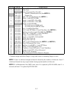
NOTE: Control box assemblies on units manufactured before October 2000 were built with two
single-spark ignition modules (P/N 807-1006). If an 807-1006 module fails, the control box may be
retrofitted with one dual-spark ignition module (Item 7 – P/N 807-3366) and two RAJAH connectors
(Item 28 – P/N 807-3484). If this option is chosen, the earlier style ignition cables (Item 24 – P/N
807-1709) must also be replaced with the new ignition cables (Item 23 – P/N 106-0676SP).