


7-4
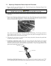
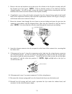
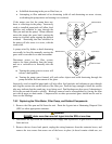
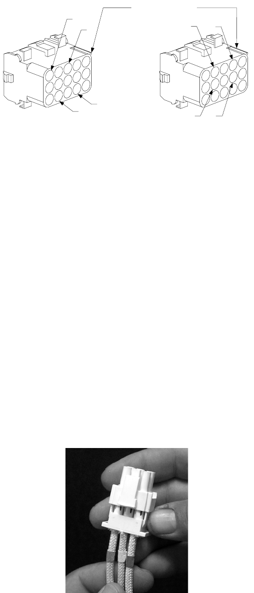
6. If a temperature probe was replaced, insert the probe leads into the connector (see left
illustration below). For full-vat units or the left half (as viewed from the rear of the fryer) of a
dual-vat unit, the red lead goes into position 6 and the white into position 7. For the right half of
a dual-vat unit (as viewed from the rear of the fryer), the red lead goes into position 12 and the
white into position 13.
Rib marks Position 1
6
7
12
13
Probe Lead Positions High-Limit Lead Positions
11
10
4
5
If a high-limit thermostat was replaced, insert the leads into the connector (see right illustration
above). For full-vat units or the left half of a dual-vat unit (as viewed from the rear of the fryer),
the leads go into positions 4 and 5 of the connector. For the right half of a dual-vat unit (as
viewed from the rear of the fryer), the leads go into positions 10 and 11. In either case, polarity
does not matter.
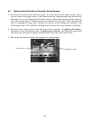
7. Reinstall the back panels and tilt housing to complete the installation, then reverse steps 1 and 2
to return the fryer to service.
7.5 Replacing a Heating Element
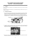
1. Perform steps 1-3 of section 7.4, Replacing a Temperature Probe.
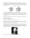
2. On dual-vat fryers, and on full-vat fryers where the temperature probe is attached to the element
being replaced, disconnect the wire harness containing the probe wiring (connector C6). Using a
pin pusher, disconnect the probe wires from the connector.
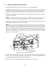
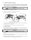
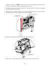
3. On the front of the contactor box, disconnect the 6-pin connector for the left element (as viewed
from the front of the fryer) or the 9-pin connector for the right element and pull the harness out
through the rear of the fryer. Press in on the tabs on each side of the connector while pulling
outward on the free end to extend the connector and release the element leads (see photo below).
Pull the leads out of the connector and out of the plastic wire loom.
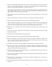
4. Raise the element to the full up position and disconnect the element springs.