


MASTER JET CF SERIES ATMOSPHERIC GAS FRYERS
CHAPTER 1: SERVICE PROCEDURES
1-30
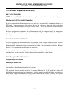
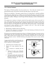
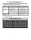
ROBERTSHAW-UNITROL 7000 SYSTEM CHECK
1. Complete System Check
With thermostat contacts closed and gas cock
dial in the “ON” position, the main burner
should ignite. Measure the reading between
the 2 & 3 terminals. If the reading is more
than 100MV, replace the gas valve.
2. System Resistance Check
With thermostat contacts closed and main
burner “ON”, measure the millivolt reading
between the 1 and 3 terminals. The reading
should be less than 80MV. If not, recheck the
thermostat leads and connections. Replace
with new or heavier gauge wires if necessary.
If the reading is still greater than 80MV,
replace the thermostat.
3. Automatic Pilot Dropout Check
With the thermostat contacts open, hold the
gas cock knob depressed with the pilot lit until
the maximum millivolt output is observed
between the 1 and 2 terminals. Then
extinguish the pilot and observe the meter.
The sound of the pilot magnet dropping should
be audible. This dropout should occur
between 120MV and 30MV. If it occurs
outside these limits, change the gas valve.
TH
TP
TH
TP
TP
THTP TH
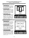
Millivolt Operator
Terminal Panel
(Robertshaw)
1
2
3
Test
Meter
Setting
Meter Leads
On Terminals
Acceptable
Results
1 MV 2 & 3 <100MV
2 MV 1 & 3 <80MV
3 MV 1 & 2 30-120MV
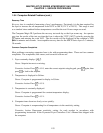
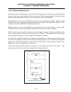
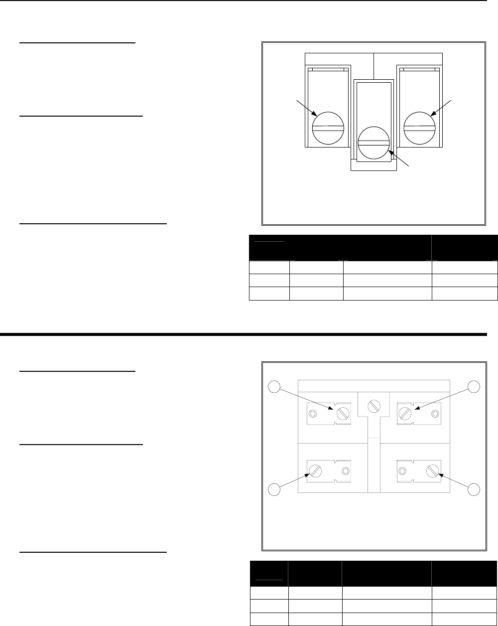
HONEYWELL SYSTEM CHECK
1. Complete System Check
With thermostat contacts closed and gas cock
dial in the “ON” position, main burner should
ignite. If not, measure across terminals 2 and
3 as indicated in the diagram. If the reading is
more than 180MV, replace the gas valve.
2. System Resistance Check
With thermostat contacts closed and main
burner “ON”, measure the millivolt reading
between terminals 1 and 3 as indicated in the
diagram. The reading should be 220MV or
less. If not, recheck thermostat leads and
connections. Replace with new or heavier
gauge wires if necessary. If the reading is still
greater than 220MV, replace the thermostat.
3. Automatic Pilot Dropout Check
With the thermostat contacts open, hold the
gas cock knob depressed with the pilot lit until
the maximum millivolt output is observed
between terminals 1 and 2. Then extinguish
the pilot and observe the meter. The sound of
the pilot magnet dropping should be audible.
This dropout should occur between 110MV
and 36MV. If it occurs outside these limits,
change the gas valve.
TH
TH
PP
PP
4
3
1
2
Millivolt Operator
Terminal Panel
(Honeywell)
Test
Meter
Setting
Meter Leads On
Terminals
Acceptable
Results
1 MV 2 & 3 <180MV
2 MV 1 & 3 <220MV
3 MV 1 & 2 36-110MV