


MASTER JET CF SERIES ATMOSPHERIC GAS FRYERS
CHAPTER 1: SERVICE PROCEDURES
1-3
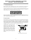
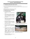
1.1 Functional Description (cont.)
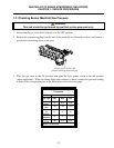
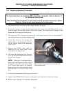
Test
Meter
Setting Pins Results
12 VAC Power to Controller 50 VAC Scale 1 and 3 of J2 12-18
24 VAC Power 50 VAC Scale 24 VAC Terminals 22-28
24 VAC Power to Gas Valve 50 VAC Scale 6 on J1 and GROUND 22-28
120 VAC Power 250 VAC Scale 7 and 12 of J1 110-125
Probe Resistance* R x 1000 OHMS 2 and 3 of J1 **
FREQUENTLY USED TEST POINTS FOR MODELS WITH INTERFACE BOARDS
** Disconnect 15-Pin harness from controller before testing probe circuit.
** See Probe Resistance Chart at end of chapter.
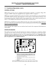
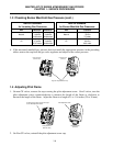
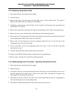
Four LEDs, arranged across the top of the boards and identified in the table below, are provided to
assist in troubleshooting.
GV
Indicates 24 VAC to the gas valve
AL
Indicates open Drain Safety Switch (if installed)
24V
Indicates 24 VAC from transformer
COMP
Indicates 12 VAC to computer
MASTER JET SERIES INTERFACE BOARD
LED DIAGNOSTIC LIGHTS
Every board contains one heat relay (K3), and may contain two basket lift relays (K1 and K2). As
shipped from the factory, fryers with bell-crank basket lifts will have relays K1, K2, and K3. All
other factory-original fryers will have boards with only relay K3.
NOTE: The basket lift option is not available on MJCF Series fryers. The above diagnostic
tables are not applicable to user-supplied or KFC-1 computers.
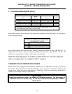
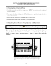
THERMOSTATS AND TEMPERATURE PROBES
MJCF Series fryers equipped with thermostat controls have an adjustable controlling (operating)
thermostat. The temperature at which the thermostat opens and closes is adjusted by changing the
setting of the thermostat with an attached knob. When new, the Fenwal controlling thermostat is
sensitive to one-degree changes in temperature.
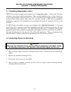
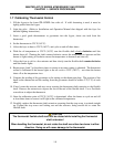
CAUTION
Fenwal thermostats are used in a number of Frymaster products. The thermostat for
the MJCF Series is 4 inches long. Do not use 3-inch Fenwal thermostats in MJCF
Series fryers.