


15
G
14
G
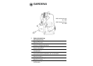
1
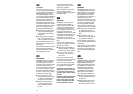
Water drain screw
2
Suction side
3
Pump fitting 33.3 mm (G1)
4
Filler cap with screw plug
5
Electronic Manometric Switch
6
Inlet, delivery side
7
RESET button
8
Light-emitting diodes
9
Screws for casing attachment
0
Casing cover
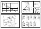
A
Turbine
B
Turbine axle
C
Rotary switch for non-return
valve
D
Mains connector for the
Manometric Switch
E
Connector socket for
pump connector plug
F
Mains plug for pump
G
Outlet, delivery side
4. Functional Parts (ill.B/C/E)
5.1 Mounting the Electronic
Manometric Switch
The Electronic Manometric Switch
5
is fitted with a 33.3 mm (G1)
outer thread at the inlet side
6
.
To mount the Electronic Mano-
metric Switch proceed as follows:
1. Hold the top of the Electronic
Manometric Switch with one
hand and with the other, screw
the lower rotating part into the
inner thread of the pump.
Screw up to the limit.
Note:When the limit has been
reached, the non-return valve
(13a) can be turned in the
counter-clockwise direction
– a maximum of one turn
however – into any position
which is the most convenient
for you.The display can also be
turned into any desired position
before the connection on the
pressure side
3
/
G
is tight-
ened up.
2. Plug the mains plug for the
pump
F
into the connector
socket
E
at the back of the
display for the Electronic
Manometric Switch (ill. E).
5.2 Location and Filling of
the Pump before Operation
1. Locate the pump at safe
distance of the liquid.
Take care that the site is firm
and solid, in order to ensure
safe location of the pump.
2. Before operation, fill the
pump either a) through the
filler cap, or b) through the
outlet nozzle of the Elec-
tronic Manometric Switch
with at least 2 I of the liquid
to be pumped:
a) To fill the pump through
the filler cap
4
: Undo the
screw plug at the filling
nozzle and tighten up again
after filling the pump (do
not use a wrench).
b) To fill the pump through the
outlet nozzle on the delivery
side
G
of the Electronic
Manometric Switch:
1. Set the rotary switch/non-
return valve to position 2
(non-return valve open).
2. Open the screw plug
of the filler cap
4
(for
bleeding).
3. Fill the pump with liquid
through the outlet on the
delivery side
G
of the
Electronic Manometric
Switch until liquid exits
the pump on the suction
side
2
.
4. Tightly close the screw
plug again.
As well as the pump itself,
the suction hose with back-
flow preventer shall be filled
in order to ensure trouble-
free drawing (refer to the
section “Suction hose con-
nection”).
5.3 Suction hose connection
Suction Side
2
1. Screw one of the two supplied
pump fittings
3
onto the
suction side
2
of the pump
and tighten it by hand until
the washer fits closely.
Note: For the suction side use
a vacuum-resistant suction
hose with back-flow pre-
venter (e.g.GARDENA Suc
tion Unit, art.no.1411). Only
this way, the suction hose can
be filled up before initial opera-
tion. Additionally, the liquid to
be pumped stays in the suction
hose, when the pump cuts
out.Thus easy priming is
made possible when starting
the pump again. For suction
heights exceeding 4 m, we
recommend to fix additionally
the suction hose, e.g.by fas-
tening it to a wooden peg, thus
the pump is relieved of load.
2. Before connection, equip the
union nut of the suction hose
with the supplied dirt filter (ill.
D). First of all remove the flat
packing which may be in the
union nut.
Note: Alternatively, you can
also use the GARDENA Pump
Preliminary Filter, art. no.1730/
1731.It is especially recom-
mended for use with highly
contaminated or with a very
sandy liquid. Filtration of water
is essential to prevent the Elec-
tronic Manometric Switch from
internal contamination, thus
avoiding malfunction of the unit.
3. In case of permanent, indoor
installation of the pump for
domestic water supply, in order
to reduce noise and to avoid
damages at the Manometric
Switch caused by vibration,
it is recommended to connect
the Pressure Tank Unit via
flexible suction lines, e.g.in
conjunction with the GARDENA
Bore Hole Suction Hose,
art.no.1729, to the pipe net-
work but not firmly via rigid
pipes.
5. Preparations prior to Operation
Please read these operating
instructions thoroughly.Follow
the information given.Use the
operating instructions to get
acquainted with the operating
parts and the proper use of
the Pressure Tank Unit.
A
For safety reasons,
people who are not
familiar with these operating
instructions should not use
this Pressure Tank Unit.
Following the operating instruc-
tions supplied by the manufac-
turer is a prerequisite for the
proper use of the pump.
The operating instructions include
all necessary instructions con-
cerning operation, maintenance
and service.
GARDENA Pressure Tank Units
4000/4 electronic plus, 4000/5 electronic plus
1. Information concerning the Operating Instructions
GARDENA Pressure Tank Units
have been designed for private
use around house and garden.
Pressure Tank Units are pre-
dominantly used for operating
watering implements and systems
in private gardens.
Besides, the GARDENA Pres-
sure Tank Units can be used for
domestic water supply, e.g.when
taking rainwater for domestic
use.
A
GARDENA Pressure Tank
Units are not designed for
continuous operation (e.g. in-
dustrial application, continuous
circulating operation).
Corrosive, easily combustible,
aggressive or explosive sub-
stances (e.g. petrol, petroleum,
nitro thinner) as well as food
must not be pumped.
The temperature of the liquid to
be pumped should not exceed
35°C.
2. Product Use
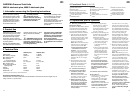
4000/4e plus 4000/5e plus
Rated power 800 W 1,000 W
Max. delivery capacity 3,600 l/h 3,600 l/h
Max. delivery head 42 m 50 m
Max. pressure
(= cut-out pressure) 4.2 bar 5.0 bar
Cut-in pressure approx. 2.2 ± 0,2 bar 2.2 ± 0,2 bar
Max. suction head 9 m 9 m
Perm. internal pressure
(delivery side) 6 bar 6 bar
Voltage 230 V 230 V
Frequency 50 Hz 50 Hz
Noise level L
WA
1)
77 dB(A) 79 dB(A)
1) Measuring method according to directive 2000/14/EC
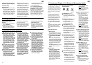
Performance Characteristics (ill. A)
Technical data of the above performance characteristics is measured at a suction height of 0.5 m,
using a 25 mm (1”) suction hose.
3.Technical Data