


Part # 4521635 (03/04/08)Page 16
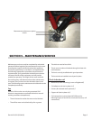
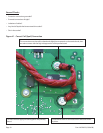
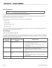
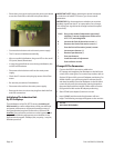
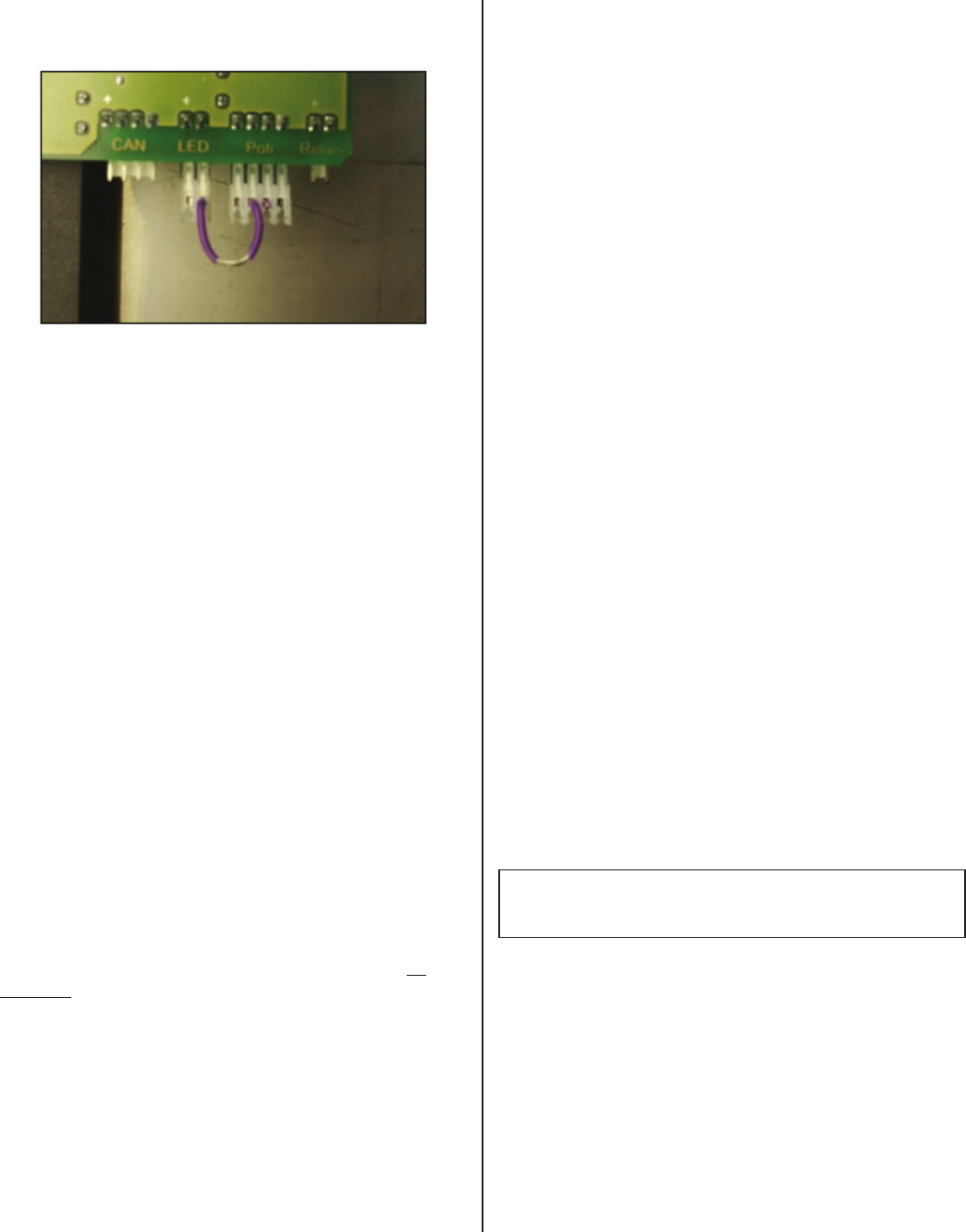
• Place short circuit service plug into the power print board
across the (Poti-LED) as showed in the photo below.
• Connect the induction unit to the main power supply.
• The CU sensors initialize automatically.
• After successful initialization, the green LED on the small
CPU-print (board) illuminates.
• In case the system nds an error during initialization, the
red LED will illuminate.
• Disconnect the induction unit from the main power
supply.
• Check the CU sensors at the plug by means of the Ohm
meter.
• Re-start the procedure of initialization.
• Disconnect the unit from the main power supply.
• Remove the short circuit service plug from both the Poti
and LED connections.
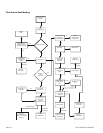
Initializing The Induction Unit
By PC Or Laptop
The initialization of the CU (RTCS) sensors (excluding all
WOK models), as well as adjustments of the pan detection
and power performance, can be performed by means of
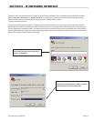
the hyperterminal program. Please refer to Section 9 “IR
Interface” for instructions on how to use the hyperterminal
program The following adjustments must be done in the
hyperterminal program: 2400bps, 8bit, no parity, 1 stop bit,
hardware protocol.
IMPORTANT NOTE: When replacing the power board and
or induction coil with RTCS sensors, you must reset all
parameters.
IMPERATIVE! Pay close attention to whether you receive a
feedback signal from the PC or Laptop after every change.
This will be your signal that the change has been accepted
successfully.
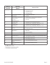
12345 Entry to the mode of adjustment (password)
; Initialize Cu sensor (temperature of the coil ca.
25°C/77°F) excluding WOK.
N Increase the limit of the mains current (+)
n Decrease the limit of the mains current (-)
“ Save the limit of the mains (power) current
T Increase pan detector (+)
t Decrease pan detector (-)
= Save pan detector
-? Leave the mode of adjustment
. State software version
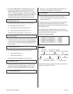
Change Of The Parameters
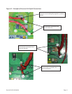
1. Connect the RS232 connection cable to the
PC/Laptop and straighten the IR-adapter to the left lower
corner of the ceran glass. For counter top cookers, refer to
Section (9) gure #3 for correct IR adapter positioning. For
all Wok cookers, you will be required to remove the top
wok bowl assembly. Place the IR-adapter in the left hand
corner directly over the rectangular opening located on
the metal sheet with ferrit stripes. Please refer to Section
(9) gure #4 for Wok cooker IR adapter positioning.
2. Start HT2400 (see chapter 9) and turn unit on!
3. Input “12345” and the mode of adjustment will now
begin. The following message will appear on the monitor:
IR= On
WELCOME REPAIRMEN