


3
BACKGUARD INSTALLATION INSTRUCTION
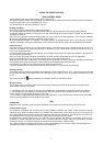
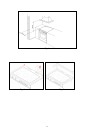
1) Remove n°2 screws fixing worktop as shown in fig.4
2) Place front part of the backguard and attach it from bottom side with the two removed screws (point 2) as shown in
fig .5
3) Fix the front part of the backguard with the screws supplied with the backguard kit (fig.6)
4) Assemble back part with front part of the backguard and fix them with a screws supplied with the backguard kit
(fig.7)
APPLIANCE ELECTRIC CONNECTION:
The electric connection must comply with the current legal standards and regulations.
Before making the connection, check that:
- The system electrical rating and the current outlets are adequate for the maximum power output of the appliance (see
the label applied to the bottom of the casing).
- The outlet or the system is equipped with an efficient ground connection in accordance with the current legal standards
and regulations. The company will not be responsible for the non-compliance with these instructions.
When the connection to the power supply network is made using an outlet:
- If the power cord is supplied without a plug, apply a standard plug that is suitable for the load indicated on the label.
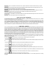
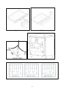
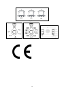
Connect the wires according to the diagram shown in FIG.8 and check that:
letter L (phase) = brown wire;
letter N (neutral) = blue wire;
ground symbol
= green-yellow wire;
- The power cord must be positioned so that an overtemperature of 75 K will not be reached at any point.
- Do not use reductions, adapters or splitters since they might cause false contacts and lead to dangerous overheating.
When the connection is made directly to the electric network:
- Use a device that ensures disconnection from the mains in which the contacts are opened to a distance that permits
complete disconnection according to the conditions for over-voltage category III.
- Remember that the ground wire must not be interrupted by the circuit-breaker.
- As an alternative, the electric connection can also be protected by a high-sensitivity residual current circuit-breaker.
- It is highly recommended to attach the special green-yellow ground wire to an efficient ground system.
WARNING: If the power cord is replaced, the ground wire (yellow-green) connected to the terminal, should be
longer than the other wires by about 2 cm.
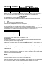
TYPES OF POWER CORDS
The appliance is equipped with a terminal for the electric connection placed behind, which is accessible removing the
posterior casing (Fig.9)
The cable of alimentation can be :
Operation at 220-240V~ : use a H05BB-F three-wire cable (cable 3x4 mm²)
Operation at 380-415V2N~ : use a H05RR-F o H07RN-F four-wire cable (cable 4x4 mm²)
Operation at 380-415V3N~ : use a H05RR-F o H07RN-F five-wire cable (cable 5x1,5 mm²)
Fig.10
The power supply cable is suitable for appliance operating on 220-240 V~
ATTENTION: The appliance conforms with the regulations of directives 2009/142/CE(ex 90/396/EC) (Gas
Directive) regarding gas appliances for domestic use and the like, 2006/95/CE (Low Voltage Directive) regarding
electrical safety and 2004/108/CE, (EMC Directive) regarding electromagnetic compatibility.
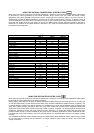
Electrical requirements
220-240V~ - 10000W( induction 7100W) (45 A max)
380-415V2N~ 10000W( induction 7100W) (32 A max/phase).
380-415V3N~ 10000W( induction 7100W) (16 A max/phase).