


—-
—
-.
—.-
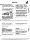
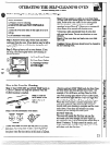
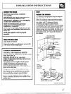
2. wiring
L Connectlengthofcopperbuildingwireto
rangeterminalblock.
B. Splicecopperwiresto aluminumwiringusing
specialconnectorsdesignedand U.L.approved
forjoiningcopperto aluminum,andfollowthe
connectormanufacturer’srecommended
procedureclosely.
NOTE:Wireused,locationandenclosureof
splices,etc.,mustconformto goodwiring
practiceandlocalcodes.
!$
Framegroundedto neutralofappliance
througha link.Ifused in a MOBILEHOMEor
ifLOCALCODESdonot permitgrounding
throughthe neutral
1)disconnectthe linkfromneutral,
2) use groundingterminalor leadto ground
unitin accordancewithlocalcodes,and
3) connectneutralterminalor leadtobranch
circuitin usualmanner.
(lfthe applianceis to be connectedby
means ofa cord set.use 4-conductorcord
4TH GROUNDING LEAD + ~
G
—
.
6
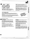
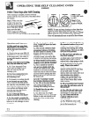
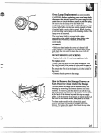
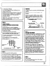
AN!AAJ’TI-T’IPbracketis suppliedwithinstructions
forinstallationina varietyofiocationseThe
instructionsincludea template,a partslistanda
listoftoolsnecessaryto completethe installation.
Readthe IMPORTA.I’$ITSAFETY
H’w3TRumoNs
andthekkruct~ons that fit
yoursituationbefore
beginninginstallation.
1. mustbe securedbyANT’I-TIPbracket
supplied.
2. Seeinstructionsto install(suppliedwith
bracket).
3. Unlessproperlyinstalled,rangecouldbe
tippedby steppingor sittingondoor.Injury
mightresultfromspilledhot liquidsorfi=om
rangeitself.
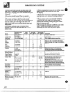
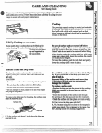
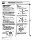
Typicalinstal!ationofAnti-Tipbracket
AttachmenttoWall
Bracket
ScrewMust
VvWi%tlf?
WimdorMetal
I
\
The
r
ANTI-TIPbracket (allowfor somesideto side
adjustment).f!llowa minimumclearanceofl/8~f
betweenthe rangeandthe levelingfootthat is to
be installedintothe ANTI-TIPbracket.
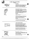
Checkthe rangeforproperinstallationintothe
A.NTI-’HPbracket (afterthe rangehas been
properlyinstalled)bygraspingthe edgesofthe
REARburner holesandcarefullyattemptingto
tiltthe rangeforward.
8
I%sure allswitchesare in the “off”position
beforeleavingthe range.
29