


.-1
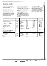
WARNING:
CONNE~OR
BLOCK IS
APPRO~D
FOR COPPER
~RE
CONNE~ON
ONLY.
2.
Muminum
Wiring
A.
Connect length of copper building wire to
range terminal block.
B.
Splice copper wires to aluminum wiring using
special connectors designed and
U.L.
approved for
joining copper to aluminum, and follow the
connector manufacturer’s recommended
procedure closely.
NOTE: Wire used, location and enclosure of
splices, etc., must conform to good wiring practice
and local codes.
STEP 5
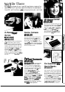
4*IRE
SYSTEM
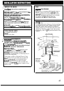
SPECIAL GROUNDING INSTRUCTIONS
WARNING:
Frame grounded to neutral of appliance through a
link. If used in a MOBILE HOME or if
LOCAL
CODES do not permit grounding through the
neutral:
1) disconnect the link from neutral,
2) use grounding terminal or lead to ground unit in
accordance with local codes, and
3) connect neutral terminal or lead to branch
circuit in usual manner.
(If the appliance is to be connected by means of a
cord set, use 4-conductor cord for this purpose.)
/
CONNECTOR
BLOCK
4TH GROUNDI
GROUND
LUG
1
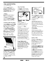
STEP 6
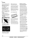
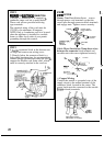
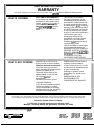
ANTI-TIP BRACKET INSTALLATION
AN
ANTI-TIP bracket is supplied with instructions
for installation in a variety of locations. The
instructions include a template, a parts list and a
list of tools necessary to complete the installation.
Read the
IMPORT~T
SAF~
INflRUCTIONS
and the instructions that fit your situation before
beginning installation.
WARNING
1.
Range must be secured by ANTI-TIP bracket
supplied.
2. See instructions to install (supplied with
bracket).
3. Unless properly installed, range could be tipped
by stepping or sitting on door. Injury might result
from spilled hot liquids or from range
itseti.
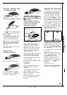
Typical installation of Anti-Tip bracket
Attachment to Wall
Bracket
Screw Must Enter
Wood or Metal
h,
I
Wall Plate
k
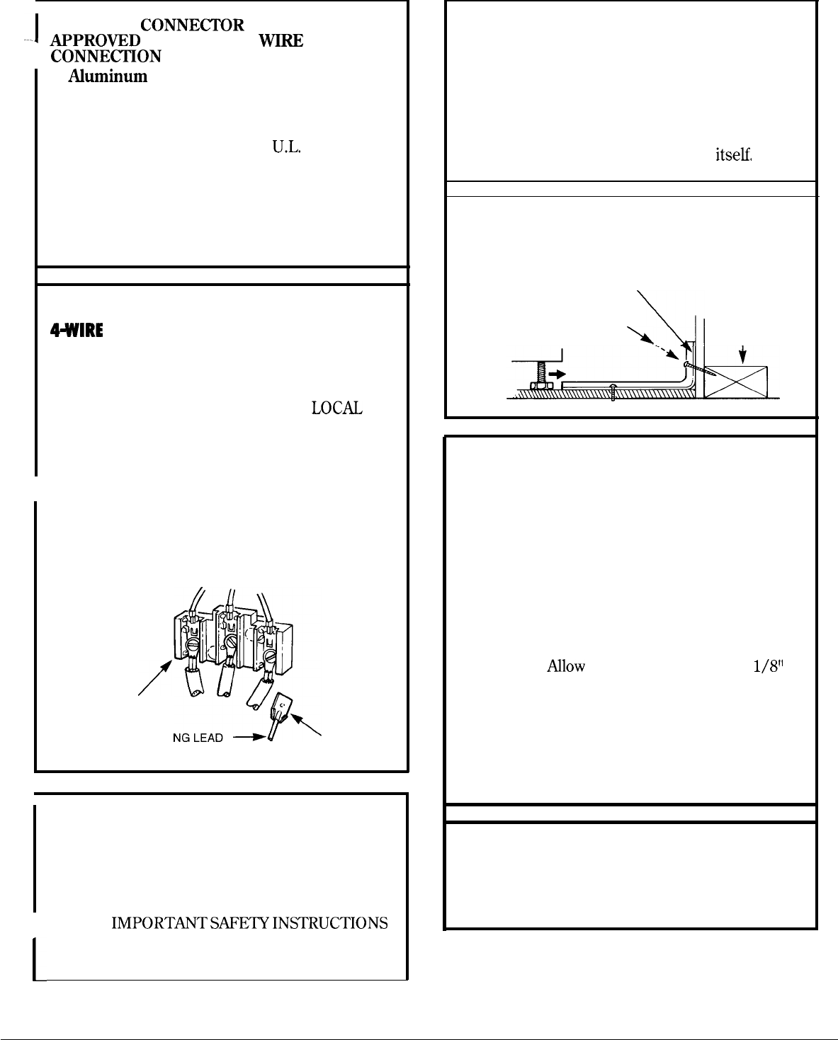
STEP 7
LEVELING THE RANGE
The
range must be leveled. Leveling feet are
located on each corner of the base of the range.
Remove the storage drawer and rotate the leveling
feet in or out as required. To remove drawer, pull it
out all the way, tilt up the front and remove it. To
replace, insert glides at back of drawer beyond
stop on range glides. Lift drawer if necessary to
insert easily.
One of the rear leveling feet will engage the ANTI-
TIP bracket (allow for some side to side
adjustment).
Nlow
a minimum clearance of
1/811
between the range and the leveling foot that is to
be installed into the ANTI-TIP bracket.
Check the range for proper installation into the
ANTI-TIP bracket (after the range has been
properly installed) by grasping the edges of the
REAR burner holes and carefully attempting to tilt
the range forward.
STEP 8
FINAL CHECK
Be sure all switches are in the “off” position before
leaving the range.
29