


33
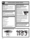
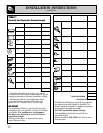
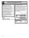
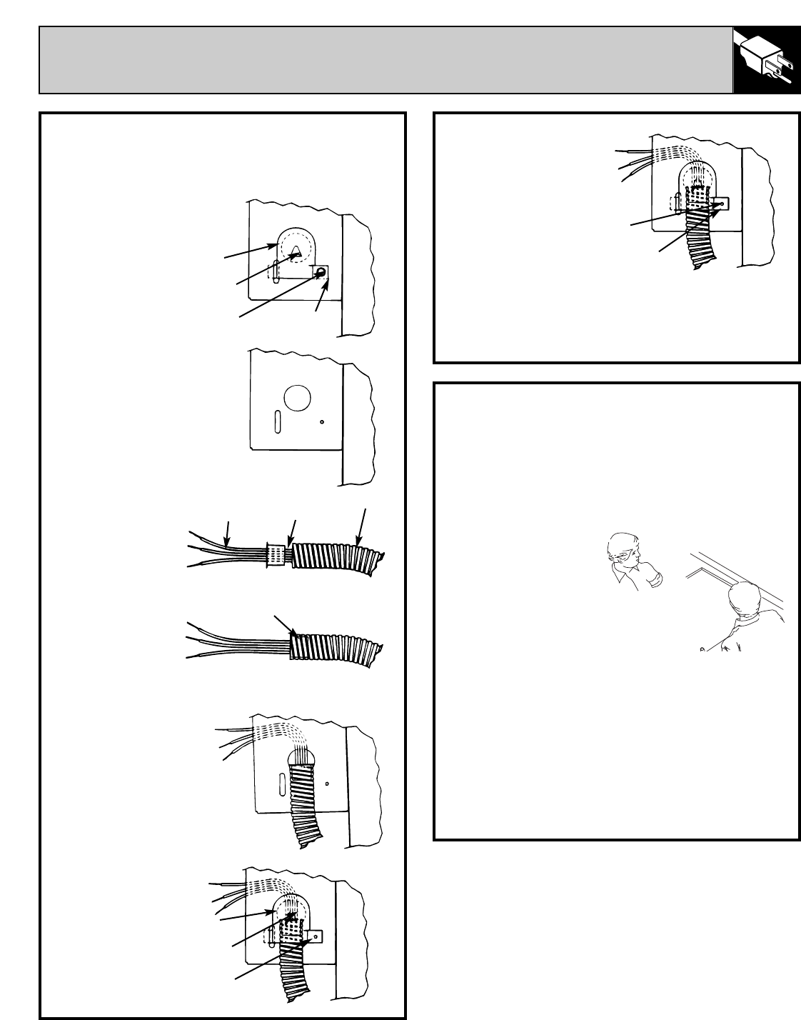
Tighten the
clamping screw
until the clamping
tab is fully seated
against the wire
compartment.
Complete the rest
of the installation observing local codes
(see Steps 9 and 10).
When complete reinstall the wire compartment
cover.
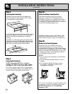
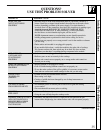
Step 8
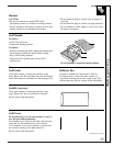
Installing the Cooktop
Remove grease jar(s) from beneath cooktop
to avoid breakage. Remove vent grille from
cooktop’s surface. Using 2 people, position
cooktop over countertop opening, with power
cable inserted through the opening.
Holding cooktop by
side edges, lower it
into countertop
opening. Replace
jar(s) and vent
grille.
Secure cooktop to the counter using the hold
down retainers and thumb screws shipped with
the unit (one on each side).
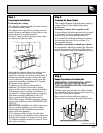
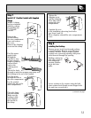
Step 7
Install 1/2″ Flexible Conduit with Supplied
Clamp
NOTE: A clamp
has been included
with the cooktop
for installing the
1/2″ flexible
conduit.
Remove the
screws holding
the wire compartment
cover and remove
the cover.
Remove the clamping
screw and the clamp.
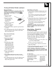
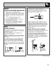
Feed the power
supply leads
through the
conduit; be sure
to leave enough
length to properly
connect these
leads to the
cooktop power
leads.
Thread the leads
through an anti-short bushing and firmly seat
the bushing in the end of the conduit.
Feed the leads
through the hole in
the wire compartment.
Lay the conduit
against the side of the
wire compartment.
Place the clamp
over the conduit.
Make sure the
bushing is fully
seated against
the stop tab in
the clamp.
Clamp
Stop Tab
Clamping
Screw
Clamping
Tab
Power Supply
Leads
Bushing (Fully Seated)
Anti-Short
Bushing
Conduit
Clamping
Screw
Clamping
Tab
Clamp
Stop Tab
Clamping
Tab
(continued next page)