


34
INSTALLATION INSTRUCTIONS
(continued)
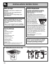
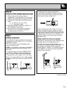
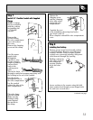
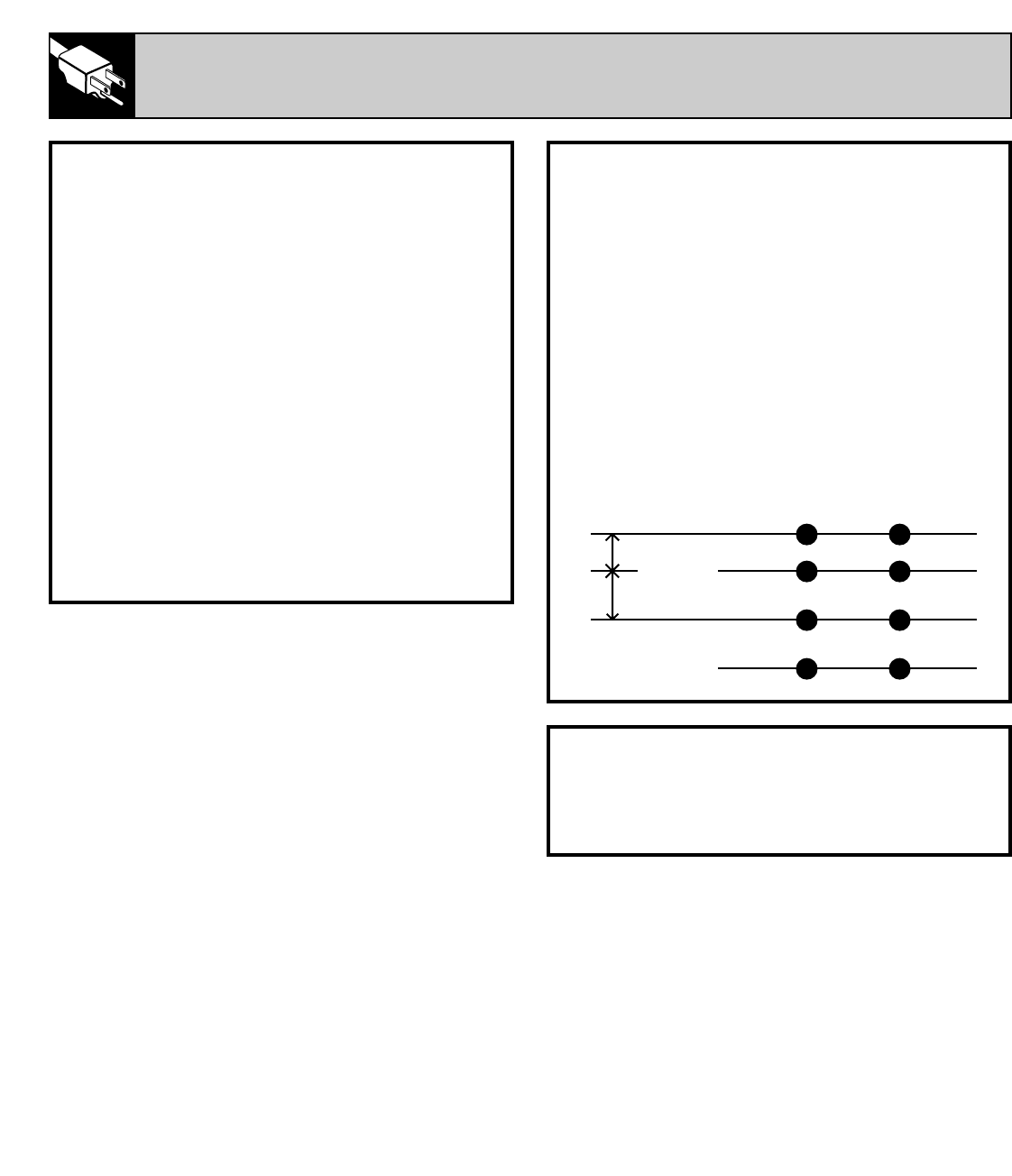
4-Conductor Branch Circuit
When connecting cooktop to a 4-conductor
circuit, connect the red leads of the cooktop and
the power supply to the branch circuit red lead;
connect the black leads to each other. Separate
the green and white leads of the cooktop.
Connect cooktop white lead to the power supply
and branch circuit neutral leads, which are white
or gray. Ground the unit by connecting the
green conductor of the cooktop to the bare or
green leads of the power supply and branch
circuit (ground leads).
4-Conductor Branch Circuit
Branch Circuit
Power
Supply
Leads
Cooktop
Power
Leads
Red Red Red
White or
Gray
White or
Gray White
Black Black Black
Bare or
Green
Bare or
Green Green
NEUTRAL
GND
120V AC
120V AC
Electrical Requirements*
Voltage Frequency KW
120/240V 60HZ 8.0KW
*For reference only. Verify with products rating plate.
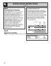
Step 9
Before Making Electrical Connections
Note to Electrician: The power leads supplied
with this appliance are U. L. recognized for
connection to large gauge household wiring.
The insulation of these leads is rated at
temperatures much higher than the temperature
rating of household wiring. The current
carrying capacity of a conductor is governed by
the wire gauge and also the temperature rating
of the insulation around the wire.
Aluminum Wiring—WARNING: IMPROPER
CONNECTION OF ALUMINUM HOUSE
WIRING TO THE COPPER LEADS CAN
RESULT IN SERIOUS PROBLEMS.
Attach copper wires to aluminum wiring using
special connectors designed and U. L. listed for
joining copper to aluminum. Follow the
connector manufacturer’s recommended
procedure closely.
Step 10
Making Electrical Connections
NOTE: The frame appli TO THE[rcuit9(iring—)]TJ/F0KW