


16
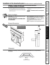
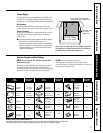
Installation of the downdraft system.
Read these instructions completely and carefully.
Step 3 is for 36
″
wide models only. Skip this step if installing a 30
″
model.
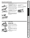
Operating Instructions
Safety InstructionsInstallation InstructionsTroubleshooting TipsCustomer Service
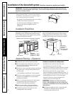
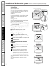
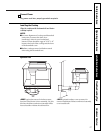
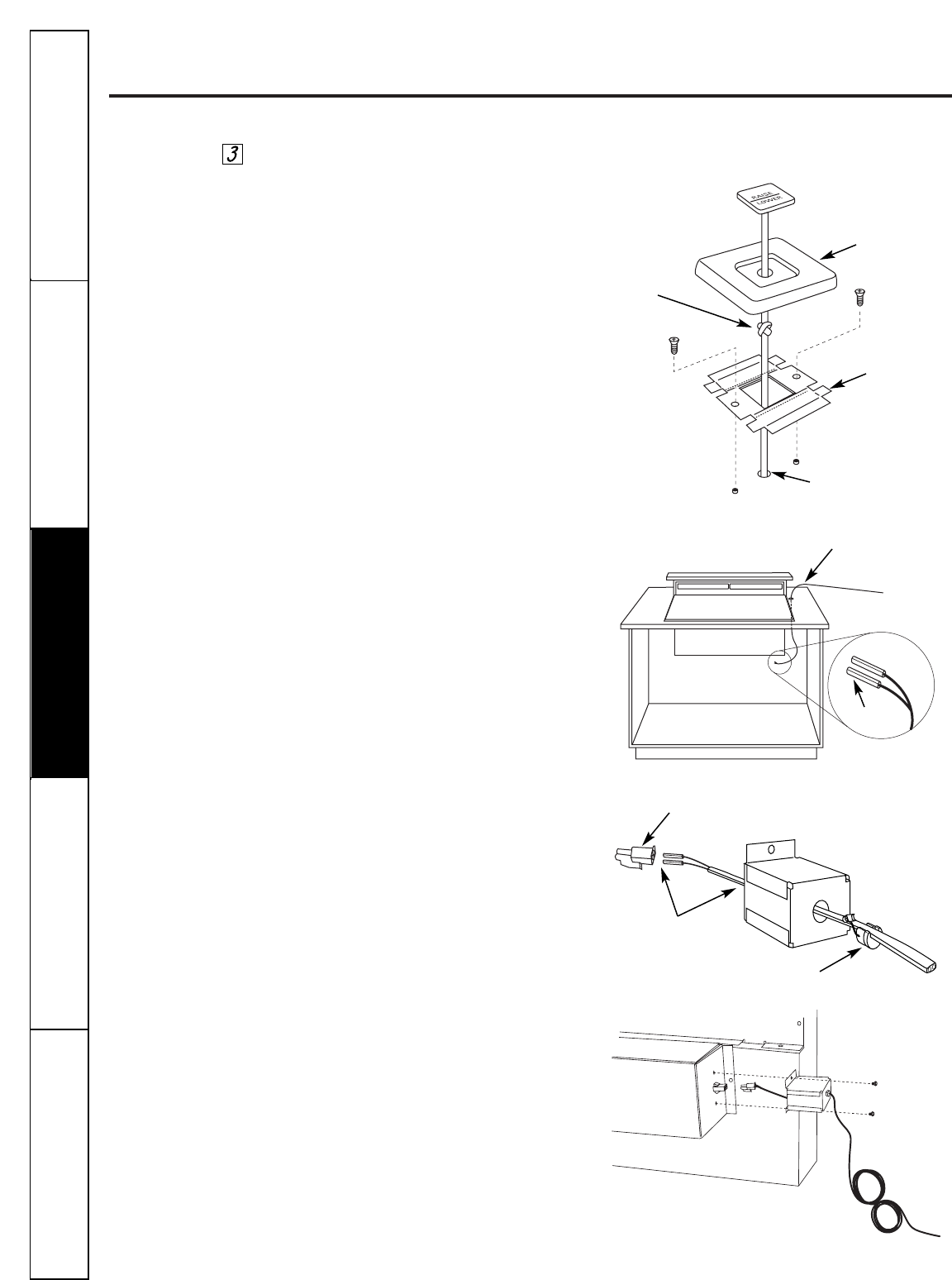
Install Raise/Lower Switch
WARNING: Disconnect eletrical power from the
unit before beginning switch installation. Failure
to do so could result in personal injury or damage
to the electrical controls.
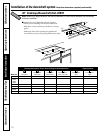
Determine the location for the RAISE/LOWER
switch. The wiring lead is 72
″
long.
■ Drill a 3/16″ hole into the desired location.
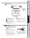
■ –If the switch is mounted into a tile surface,
drill the hole between the tiles. Use locally
approved caulking to cover any gaps.
■ Center the mounting bracket over the hole and
mark pilot holes. Remove the bracket and drill
pilot holes.
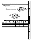
■ Mount the metal switch bracket with screws
(not provided, choose screws for your type of
countertop or use locally approved adhesive).
■ Tie a knot in the lead as close to the switch as
possible. This will prevent the lead from being
pulled away from the switch.
■ Thread the wire lead through the trim mounting
bracket and the top of the countertop as shown.
■ Pull the wire through the hole from the
underside of the countertop and thread the
wire lead into the end of the wire box.
■ Peel film from the back of the cover trim to
expose the adhesive. Press trim onto the
mounting bracket to set the adhesive.
■ Peel film from the back of the
RAISE/LOWER
pad to expose the adhesive. Align with the
impression and press to set the adhesive.
■ Remove protective coating from the top of the
trim frame.
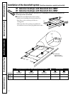
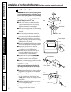
IMPORTANT: Do NOT connect wire leads to
white connector until you have threaded the
lead through the countertop hole and through
the end of the wire box.
■ Push wire metal leads into the white connector
plug. Pull wire through the box leaving about
2″ additional length.
■ Place plastic strain relief over the wire;
the wire should be flat and fit into the area.
Do
NOT
pinch or twist the wire. Snap the strain
relief closed.
■ Push the strain relief into the hole on the wire
box. It will snap into position.
■ Secure wire box to vent with screws provided.
■ Coil the excess wire and position away from
moving parts and cabinet contents.
Trim
Knot
Mounting
bracket
Thread electrical
leads through hole
2 Pin connector
3
⁄16″ Hole
Leads
Strain relief
Pull 2″ length
out of box