


– 28 –
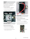
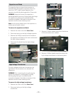
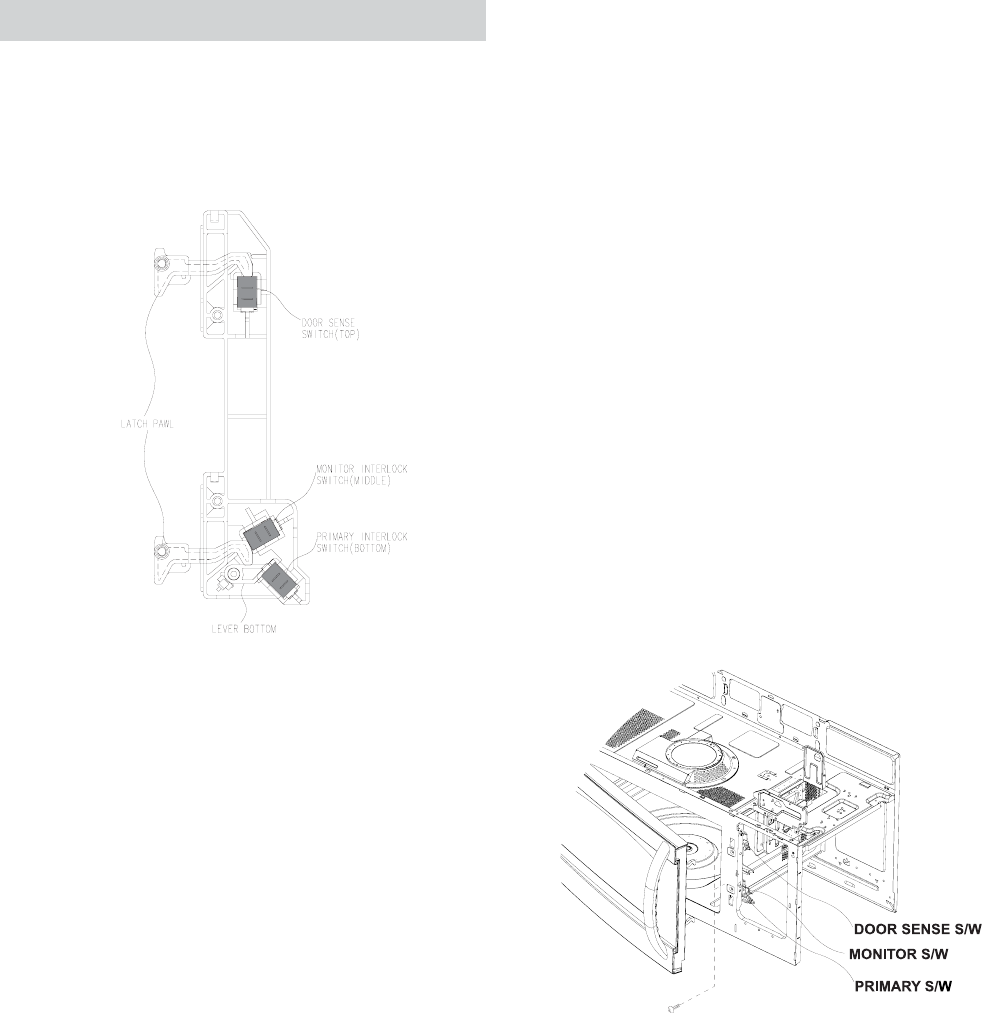
Interlocks (Door Latch Switches)
The interlocks are designed as follows:
Primary - Bottom switch operated by bottom latch
pawl connected to line (L) leg.
To test the interlocks:
Disconnect power to the oven.1.
Open the control panel.2.
Discharge the capacitor.3.
Check continuity of COM and N.O.:4.
Door Closed - 0 • Ω
Door Open - ∞ • Ω
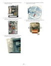
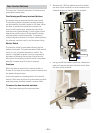
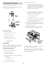
Monitor Switch
The monitor switch is located between the top and
bottom interlocks. The monitor switch is operated
indirectly by the bottom latch pawl.
To test the interlock system:
Disconnect power to the oven.1.
Open the control panel.2.
Discharge the capacitor.3.
Disconnect the monitor switch leads and test at 4.
the terminals:
Door Closed - ∞ • Ω
Door Open - 0 • Ω
5. Reconnect the switch wiring.
6. Test the circuit operation:
a. Connect temporary jumper across relay
contacts and primary switch to simulate
shorted switch contacts. Locate convenient
connections in circuit to be certain COM
and N.O. terminals are used.
b. Connect an ohmmeter (Low Scale) across
the two line terminals of the appliance
power cord. Continuity must show:
Door Closed - Some • Ω
Door Open - 0 • Ω
c. Remove the 20-Amp. fuse - the circuit must
open (∞ Ω). If not, check the wiring of the
monitor and interlock circuits.
7. After the test, remove temporary jumper leads
from interlocks and relay. Reconnect monitor
switch leads, replace fuse.
8. Replacement of any parts in monitor circuit
requires repeating this entire test procedure.
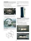
The switch housing is not adjustable. It is fi xed on
the front cavity with two screws.
IMPORTANT - CHECK FOR MICROWAVE LEAKAGE
AFTER REPLACING OR ADJUSTING DOOR, INTERLOCK
SWITCHES OR BRACKETS.