


– 21 –
during the drying cycle, drops to 700 W for gentler
drying.
Water inlet temperature must be at least 120 °F for
proper drying. Low water inlet temperature will
prevent proper convection air movement and
increase drying time substantially.
If the complaint is the dishes are not drying cor-
rectly, don’t overlook the rinse agent. A rinse agent
will improve the water sheeting action and drying
performance.
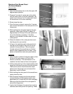
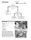
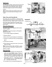
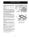
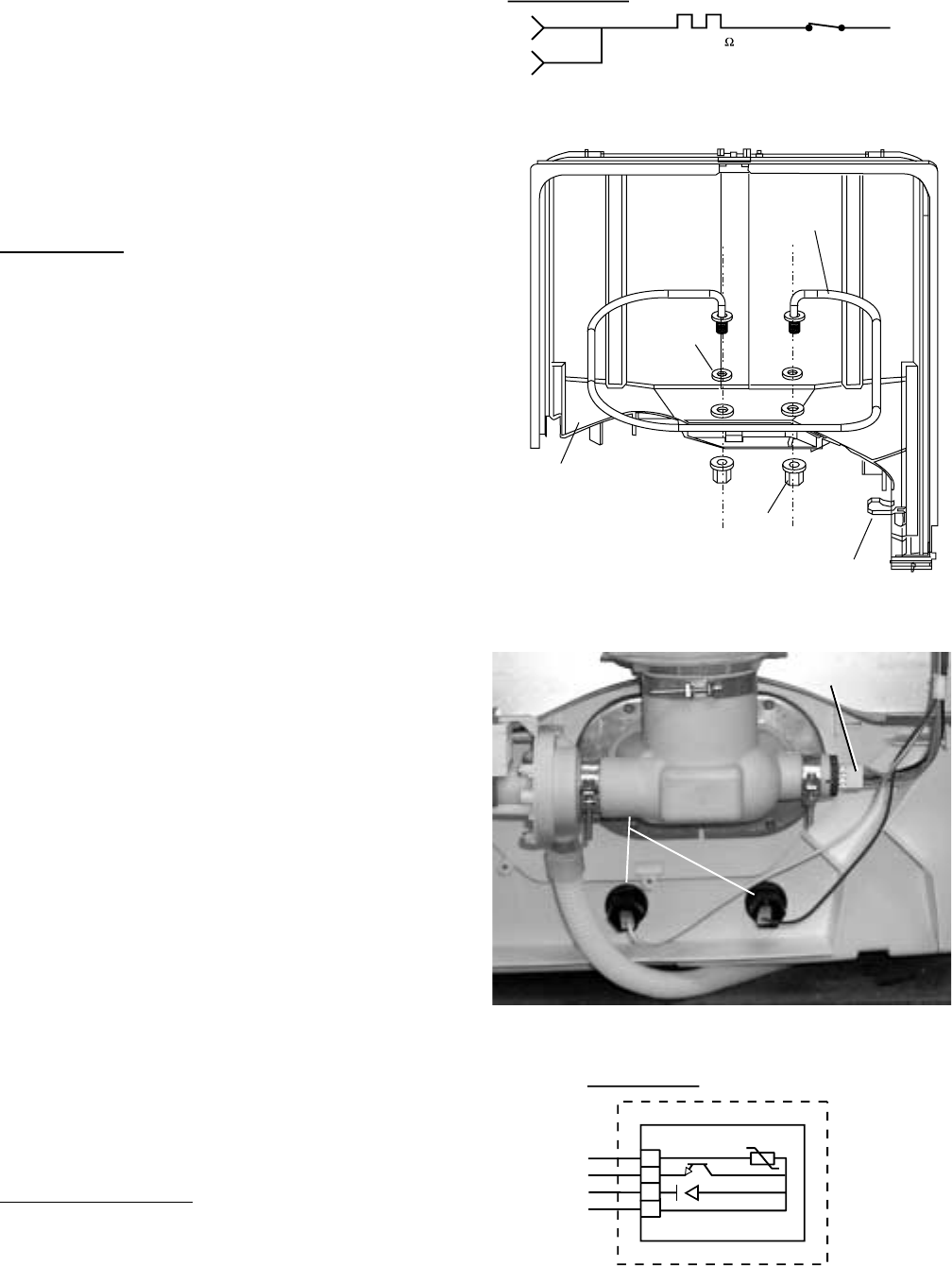
Replacement
Note: The heating element nuts are located on the
underside of the washer, near the back. Ample
force is required to remove the nuts. Removing the
dishwasher from installation may be required.
1. Disconnect power and remove wire leads from
heating element.
2. Unscrew 2 heating element nuts.
3. Remove 2 screws, 2 heating element supports,
and the heating element.
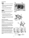
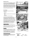
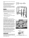
Turbidity Sensor
The turbidity sensor measures the amount of
suspended particles in the wash water in the sump.
As the sump water lays between the 1/4- to 3/8-
inch gap between the LED transmitter and the
receptor during the first fill, the baseline reading is
taken. Successive turbidity measurements are
supplied to the control module and used to deter-
mine whether any prewash or rinse cycles can be
skipped. Decisions are based on a comparison of
clean water measurements at the beginning of the
first fill, measurements taken at selected fills, and
water temperature. By measuring the turbidity level,
the control module can conserve energy on lightly
soiled loads by skipping unnecessary cycles.
Note: If the turbidity sensor circuit fails open or
shorted, the sensing LED on the control panel will
not light and the unit will operate for the maximum
amount of time, using the maximum number of
wash and rinse fills for the selected cycle.
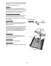
The turbidity sensor also contains the thermisteor
for automatic temperature control.
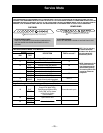
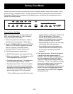
Turbidity Sensor Test
Factory test mode is the most accurate way to test
the turbidity sensor circuit (circuit contains control
module, wiring, and turbidity sensor). Refer to the
Factory Test Mode
chapter.
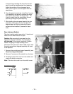
Figure 4
Tub
Nut
Heating Element
Support
Heating
Element
Heater
Grommet
Heating
Element Nuts
(Bottom View)
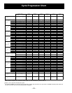
Turbidity Sensor
Turbidity Sensor
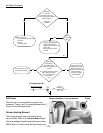
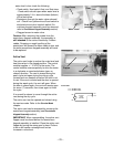
HEATING ELEMENT
J2-3
J2-4
VX
HEATING ELEMENT
19.4-19.8
NO
N
COM
WX
DOOR
INTERLOCK
WR
1
2
3
4
GY
NX
SX
OX
NTC
TURBIDITY SENSOR
Refer to
Wiring Diagram
for voltages and pin-outs.