


AT-2
LOCATING THE ANTI-TIP FLOOR
BRACKET (cont.)
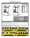
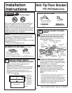
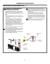
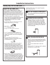
Recommended Installation
– Wood
Recommended Installation
– Concrete
Minimum Acceptable #1 –
Wall Plate Stud
Minimum Acceptable #2 –
Wood Floor
Minimum Acceptable #3 –
Concrete Floor
Figure 2 – Acceptable
Screw Placement Locations
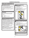
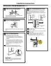
CONCRETE Wall and Floor Construction:
$QFKRUVUHTXLUHGQRWSURYLGHG
4 each 1/4” (6 mm) x 1-1/2” (38 mm) lag bolts
4 each 1/2” (12 mm) O.D. sleeve anchors
'ULOOWKHUHFRPPHQGHGVL]HKROHVIRUWKH
anchors into the concrete at the center of the
holes marked in Step 2.
,QVWDOOWKHVOHHYHDQFKRUVLQWRWKHGULOOHG
holes. Place the anti-tip floor bracket as
indicated in Step 2. Remove the locator
template from the floor.
,QVWDOOWKHODJEROWVWKURXJKWKHDQWLWLSIORRU
bracket and tighten appropriately.
WOOD Wall and TILE Floor Construction:
)RUWKLVVSHFLDOFDVHORFDWHWKHZDOOKROHV
identified in Fig. 1. Drill an angled 1/8” (3 mm)
pilot hole (approx. as shown in Fig. 3) in the
center of each hole.
0RXQWWKHDQWLWLSIORRUEUDFNHWXVLQJWKH
Minimum Acceptable Installation #1, as
illustrated in Fig. 2.
C
B
AT-3
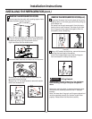
ANTI-TIP BRACKET INSTALLATION
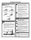
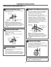
WOOD Wall and Floor Construction:
'ULOOWKHDSSURSULDWHQXPEHURIµPP
pilot holes in the center of each floor bracket
hole being used (a nail or awl may be used if
a drill is not available) AND remove the locator
template from the floor.
0RXQWWKHDQWLWLSIORRUEUDFNHWE\IDVWHQLQJ
the 2, or recommended 4, #10-16 hex-head
screws tightly into place as illustrated in
Figure 3.
A
AT-4
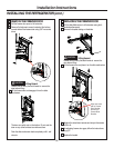
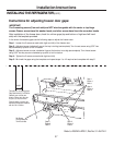
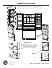
POSITIONING THE REFRIGERATOR
TO ENGAGE THE ANTI-TIP FLOOR
AND BASE BRACKETS
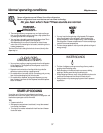
Before pushing the refrigerator into the opening,
plug the power cord into the receptacle and
connect waterline (if equipped). Check for leaks.
Locate the refrigerator’s RH side and move back
approximately in line with the RH side of the
cabinet opening, W. This should position the
anti-tip floor bracket to engage the anti-tip base
bracket on the refrigerator.
Gently roll the refrigerator back into the cabinet
opening until it comes to a complete stop. Check to
see if the refrigerator front lines up with the cabinet
front face. If not, carefully rock the refrigerator
forward and backward until engagement occurs
and you notice that the refrigerator is fully pushed
up against the rear wall.
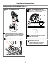
If Applicable: Adjust the rear (and front) wheel
height settings to fully engage the rear anti-tip
brackets, while also aligning the refrigerator
front with the cabinet front face.
A
C
B
D
NOTE:
If you pull the refrigerator out and away from the wall
for any reason, make sure the anti-tip floor bracket is
engaged when the refrigerator is pushed back against
the rear wall.
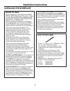
Rear RH
Corner of the
Refrigerator
Floor
Wall
Plate
Stud
Floor
Bracket
2 Screws
Must Enter
Wood or
Metal Stud
Wall
Installation Instructions
30
Figure 3 – Attachment to Wall and Floor
Refer to 239D1142P001, Pub No. 31-45484-2