


Installation
Gas Updraft Cooktop
7
•Plug power cord into properly grounded
receptacle.
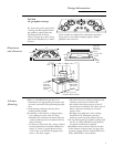
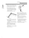
•Assemble burner as shown. Check to be sure
that burner heads are securely seated and
caps are positioned as shown.
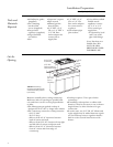
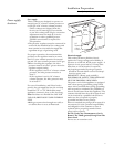
•Install the supplied pressure regulator and
nipple in the gas line as close to the cooktop
inlet as possible. Allowances for ventilation
ducting may be necessary.
–Make sure the regulator is installed in the
right direction.
•Install a manual shut-off valve in the gas line
in an easily accessible location.
Note: Instead of using solid piping to connect
to pressure regulator, an approved flexible
metal appliance connector may be used
between the pipe stub and the shut-off valve
and the pressure regulator, if local codes
permit.
– Appropriate flare nuts and adapters are
required at each end of the flexible
connector.
•Turn on the gas. Check for leaks using a
liquid leak detector at all joints in the system
(the pressure test nipple is adjacent to the
gas inlet pipe on the rear right hand side of
the cooktop bottom.
Regulator
Solid Piping
or Flexible
Connector
Shut-Off
Valve
Pipe Stub
Do not use a flame to check for
gas leaks.
IMPORTANT: Disconnect the cooktop and
the individual shut-off valve from the gas
supply piping system during any pressure
testing of that system at test pressures greater
than 1/2 psig. Isolate the cooktop from the
gas supply piping system by closing the
individual manual shut-off valve to the
cooktop during any pressure testing of the gas
supply piping system at test pressures equal to
or less than 1/2 psig.
CAUTION
IL NE FAUT PAS UTILISER
DE FLAMME POUR VÉRIFIER S’IL Y A
DES FUITES.
CAUTION
PRUDENCE
2
Install
Pressure
Regulator
Step
3
Connect
electrical
Step
4
Assemble
burners,
check ignition
Step
•Check for proper ignition:
–Push in one control knob and turn 90° to
HIGH position.
–The igniter will spark and the burner will
light; the igniter will cease sparking when
the burner is lit.
–First test may require some time, while air is
flushed out of the gas line.
–Turn knob to OFF.
–Repeat the procedure for each burner.
Burner Grate
Burner Cap
Burner Bowl
Burner Head
Electrode
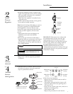
Front
Medium Head
And Cap
Medium Head
And Cap
Large Head
And Cap
Medium Head
And Cap
Small Head
And Cap
Make sure slot in burner head
is positioned over electrode