4
Installation Instructions
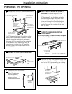
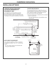
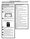
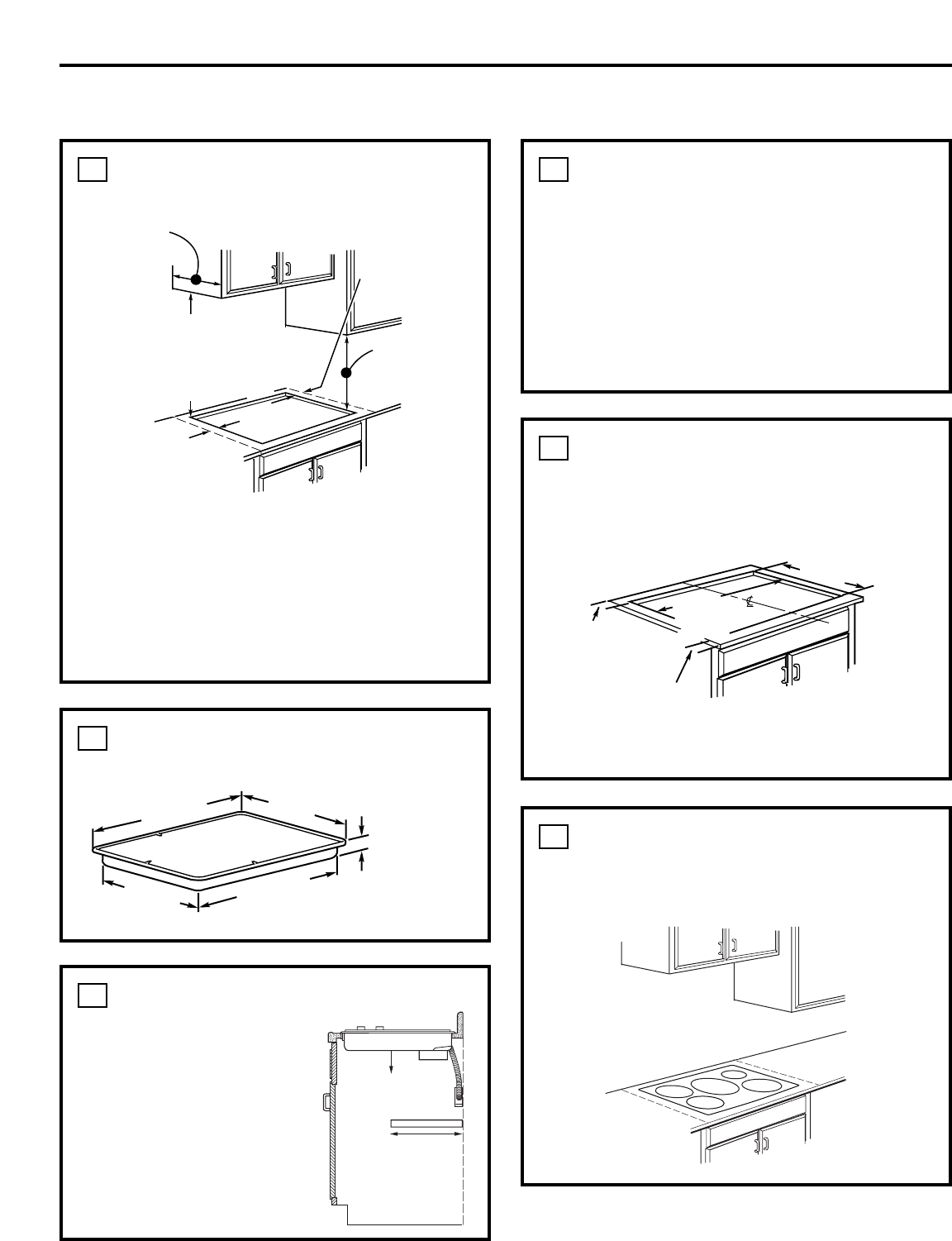
The following MINIMUM clearance dimensions
must be maintained.
1
PREPARING THE OPENING
OVERALL COOKTOP DIMENSIONS
2
Make sure the wall coverings, countertop and
cabinets around the cooktop can withstand
heat (up to 200°F) generated by the cooktop.
5
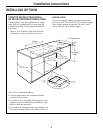
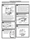
CUTOUT DIMENSIONS OF THE
COUNTERTOP
To insure accuracy, it is best to make a template
when cutting the opening in the counter.
4
13″ MAX. Depth of uprotected
overhead cabinets
30″ MIN.
Clearance from
countertop to
unprotected
overhead surface
2″ MIN. Clearance
from cutout to side
wall on the left of
the unit
15″ MIN. Height
from countertop to
nearest cabinet on
either side of unit
2″ MIN. Clearance
from cutout to
side wall on the
right of the unit
20-7/8″
(21″ SS) at center
33-5/8″
Cooktop
36″
(36-1/8″ SS) at center
18-7/8″
4-5/8“ at front
baffle
3-1/4” at rear air
intake
2-1/2″ Min.
from front edge
of cutout and
front edge of
countertop
19-1/8″ depth of cutout
33-7/8″
width of
cutout
1-3/4″ Min. Between
cutout and the wall
behind the cooktop
Wall coverings,
cabinets and
countertop must
withstand heat
up to 200°F.
If a 30″ clearance between the cooking surface
and overhead combustible materials or metal
cabinets cannot be maintained, a minimum
clearance of 24″ is required and the underside
of the cabinets above the cooktop must be
protected with not less than 1/4″ insulating
millboard covered with sheet metal not less
than 0.0122″ thick.
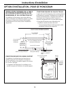
VERTICAL CLEARANCES (CONT.)
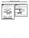
IMPORTANT: To ensure long life of the
electronic components, allow a minimum of
12″ free space for air circulation below the
cooktop bottom. (Except installation over a
single oven.) The cooktop bottom has air
intake ports toward the front that help cool
the components. Do not install a shelf or
partition beneath the cooktop that is more
than 18″ deep.
3
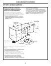
Use a 36” or wider cabinet base.
VERTICAL CLEARANCES
Allow 12” minimum
vertical clearance
between the cooktop
bottom and any
combustible surfaces.
3
12″ Min.
Vertical Clearance
18″ Max.
Deep Shelf


