


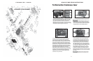
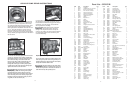
EXPLODED VIEW - GP8155-R
4
GP8155-R PUMP REPAIR INSTRUCTIONS
12) Remove the connecting rod screws (24).
Connecting rods are marked 1 to 3
for identification. Do not rotate connecting rod
halves or interchange them. When re-assembling,
the connecting rod must be fitted in their exact
original position on the crankshaft journals.
13) Push connecting rod halves together with the
crosshead as far as possible into the crosshead
guide. Remove bearing cover (14). Begin dismantling
of the reduction gear by removing screws (67). Press
off gear cover (66) by screwing two screws into both
threaded bores. Remove screw (72) and take off fitting
disc (69). Remove cogwheel from shaft with a removal
tool and take the crankshaft out of the crankcase by
gently tapping it with a rubber mallet. Remove connect-
ing rod (24) and crosshead (25) from crankcase.
Remember that this assembly must be re-assembled
exactly as it was removed. Check surfaces on connect-
ing rods (24), crankshaft (22) and crosshead (25).
Check the surfaces of the crosshead guides in the
crankcase for any uneveness.
14) Reassemble in reverse order. Replace the
connecting rod and crosshead exactly as they
were removed. Press the bearing ring (21) past
the clip ring groove. Replace the shims (21C).
Snap in the clip ring (19) and insert crankshaft
from other side, then press in the roller bearing
(20). Mount bearing cover (14) and tighten screws
(17) to 64 Ft-lbs. Adjust axial play (clearance) on
the crankshaft to minimum 0.1mm / 0.15mm
using shims (21A/B). Connecting rods must sit
exactly in the middle of the crankshaft journal.
Mount connecting rod halves in the exact, original
position and tighten to 37 Ft-lbs. The shaft should
turn easily.
Connecting rods must be able to
move slightly sideways on the stroke journals.
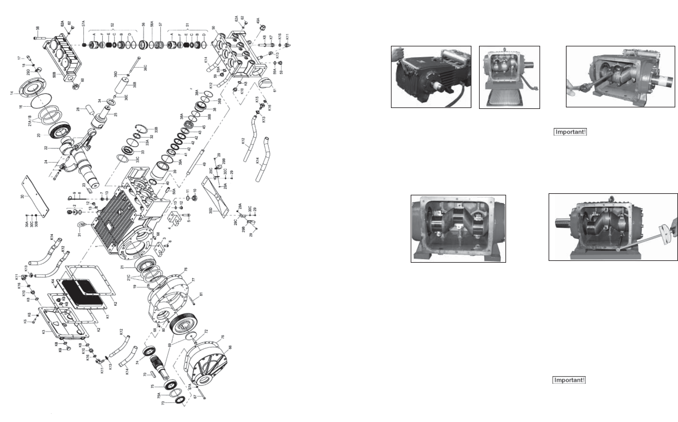
To Dismantle Crankcase Gear
11) Take out plungers and seal sleeves as described
above. Drain the oil by taking off the plug (12). After
removing the clip ring (33B), lever out the seal retainer
(33) and seal (32) with a screwdriver. Open hose
adapter (K11) and remove gear cover (K3) by removing
the socket head cap screws (K5). Remove the cooling
vane plate (K1) by removing the screws (K4)
9