


5
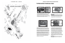
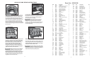
Parts List - GP8155-R
Item Part Description Qty
1 05410 Crankcase 1
2 06893 Oil Filler Plug Assy with Vent 1
3 05411 Rear Foot for Crankcase 2
4 05412 Front Foot for Crankcase 2
5 05413 Hexagon Socket Screw 4
6 05414 Hexagon Socket Screw 4
7 05381 Plug 3/8 for Oil Dipstick 1
8 05035 Oil Dipstick Assy 1
9 01009 O-Ring 1
10 05415 Plug M33*1.5 1
11 07102 O-Ring 1
12 06273 Plug G3/8 3
13 22929 Copper Washer 4
14 05036 Bearing Cover Closed 1
16 05037 O-Ring 1
17 05038 Hexagon Socket Screw M12 8
18 05039 Spring Ring 8
19 05124 Clip Ring 1
20 05416 Tapered Roller Bearing 1
21 05417 Tapered Roller Bearing 1
21A 05042 Fitting Disc 3
21B 05043 Fitting Disc 3
21C 05113 Fitting Disc 3
22 05418 Crankshaft For Turned Gear 1
23 05419 Fitting Key 1
24 05047 Conn-rod Assy 3
25 05048 Crosshead c/w Plunger 3
28 05049 Crosshead Pin 3
29 05051 Hexagon Screw 6
29A 07408 Hexagon Nut 2
29B 05420 Bracket 2 for Cooling Hose 2
29C 05421 Support Clamp 2
29D 05422 Bracket 1 for Cooling Hose 1
30 05052 Cover Plate 1
30A 07225-0100 Hexagon Screw 5
30B 13136 Grommet 5
30C 08280 Washer 9
30D 05050 Splash Cover 1
31 07623 Eye Bolt 4
32 05058 Radial Shaft Seal 3
33 05055 Seal Retainer 3
33A 05056 O-Ring 3
33B 05054 Clip Ring 3
33C 05059 Fitting Disc 3
34 05060 Oil Shield 3
36B 05280 Plunger Pipe 3
36C 05062 Tension Screw 3
36D 07665 Copper Washer 3
36E 06900 Centering Sleeve 3
38 05283 Seal Case 3
38A 13286 O-Ring 6
38B 05281 Support Ring 6
39 05275 Seal Sleeve 3
39A 05066 O-Ring 3
40 07723 Compact Ring 3
41 05276 Pressure Ring 3
42 05277 Sleeve 9
43 05278 Sleeve Support Ring 3
50A 13162 Centering Stud 2
50B 05075 Discharge Casing 1
51 05076 Suction Valve Assy. 3
51A 05077 Spring Tension Cap 3
51B 05078 Suction Valve Seat 3
51C 05079 Valve Plate 3
51D 07658 O-Ring 3
51E 05080 Valve Spring 3
51F 05081 Valve Spring Guide 3
52 05082 Discharge Valve Assy 3
52A 05077 Spring Tension Cap 3
52B 05084 Discharge Valve Seat 3
52C 05079 Valve Plate 3
52D 06258 O-Ring 6
52E 05080 Valve Spring 3
52F 05081 Valve Spring Guide 3
56 05085 Discharge Valve Adaptor 3
56A 06258 O-Ring 3
57 05086 Pressure Spring 3
57A 07210-0100 Pressure Spring 3
58 05087 Hexagon Socket Screw 12
59 07109 Plug G1/2 2
59A 06272 Copper Seal 2
60 06909 Plug G1 1/4 1
61 05088 Plug G3 1
62 05302 Plug G1/4 6
62A 06934 Copper Gasket 6
66 05423 Gear Cover 1
67 05424 Hexagon Screw 10
67A 07274 Washer 10
68 05425 Cylinder Pin 4
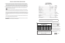
69 05426 Gear Wheel Set
(2200 RPM=3.8) 1
70 07614 Fitting Key 1
72 05427 Hexagon Screw 1
73 05428 Shaft Seal Ring for Gear 1
74 05429 Roller Bearing 1
75 05430 Roller Bearing 1
75A 05431 Fitting Disc 1
76 05432 Gear Seal 2
77 05433 Flange c/w Gear 1
78 05025 Oil Cooler 1
79 07662 Mounting Aid for Valve 1
80 07544 Hexagon Socket Screw M8 1
81 05434 Hexagon Socket Screw 9
K1 05026 Cooling Vane Plate 1
K2 05027 Seal for Gear Cover 2
K3 05028 Gear Cover 1
K4 05029 Hexagon Hd Cntrsnk Screw 8
K5 07381 Hexagon Socket Screw 8
K6 08041 Washer 8
K7 05030 Connection for Oil Cooler 1
K8 06272 Copper Seal 6
K9 07109 Plug G1/2 2
K10 05120 Connecting Branch 3
K11 05032 U-Joint Connector c/w Nut 3
K12 05033 Tube for Cooler 2
K13 05402 Hose Clamp 4
K14 05435 Hose Guard 2
K15 05404 Hose Coupling Nut 1
K16 05436 Flat Gasket 4
45 05279 Seal Tension Spring 3
49 05072 Stud Bolt 8
49A 05073 Hexagon Nut 8
50 05074 Valve Casing 1
Item Part Description Qty
8
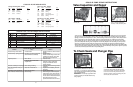
7) Be careful not to damage the seal
sleeve (39) and pressure ring (41). Check the inner
diameter of the pressure ring for wear and if neces-
sary replace together with seals (40) and (42). Clean
all parts. New parts should be lightly coated with
silicon grease before installation. Insert the seal unit
(40, 41, 42 43) into the sleeve. Push the ceramic
plunger carefully through the seals from the crank-
case side. If necessary, the seals can be held tightly
using a suitable pipe support held on the other side of
the seal sleeve.
8) Take out the seal case (38) from the valve casing
(50) and check o-rings (38A) (if necessary secure
two screwdrivers in the front o-ring groove to extract
seal casing from valve casing). Coat seals with
silicon grease before installing.
Mounting surfaces of the crankcase
and the valve casing must be clean and free of
damage. The components must lie exactly and
evenly on one another. The same exactness applies
for all centering positions in the crankcase, pres-
sure and valve casing.
9) Coat the seal sleeve(39) lightly with anti-corrosive
grease (e.g. molycote no.Cu-7439) in its fitted area
towards the crankcase. Insert the seal sleeves in to
their crankcase fittings. Coat the threads of the
tension screw (36C) lightly with thread glue and
insert it together with a new copper ring (36D)
through the ceramic pipe. Turn the pump by hand
until the plunger (25) rests against the plunger pipe.
Tighten the tension screw at 30 Ft-lbs.
Thread glue must never come between
the plunger pipe (36B) and centering sleeve (36E).
Overtensioning of the plunger pipe by excessive
tightening of the tension screw and/or dirt or damage
on the mounting surfaces can lead to plunger pipe
breakage. Insert the seal tension spring (45) and o-
ring (39A) in to the seal sleeve (39).
Replacing Valve Casing:
10) Put seal cases (38) in the centering holes of the
valve casing, then push valve casing carefully on to
centering studs (50A). Tighten hexagon screws (49A)
evenly and crosswise at 266 Ft.-lbs.
The torque tension on the screws (49A)
must be checked after 8-10 operating hours; the pump
must be at zero pressure. Thereafter, the tension is
to be checked every 200 operating hours.
GP8155-R PUMP REPAIR INSTRUCTIONS