Installation
312786G 3
Installation
15V821 Dump Valve Kit for Wall Panel
NOTE: These instructions show this kit being installed
on the A side. It may also be installed on the B side.
1. Shut off the fluid supply to the dose valve (V) at the
front of the wall panel.
2. Actuate the dose valve to relieve fluid pressure in
the valve.
3. Relieve fluid pressure upstream and downstream of
the dose valve. See your ProMix 2KS Operation
Manual.
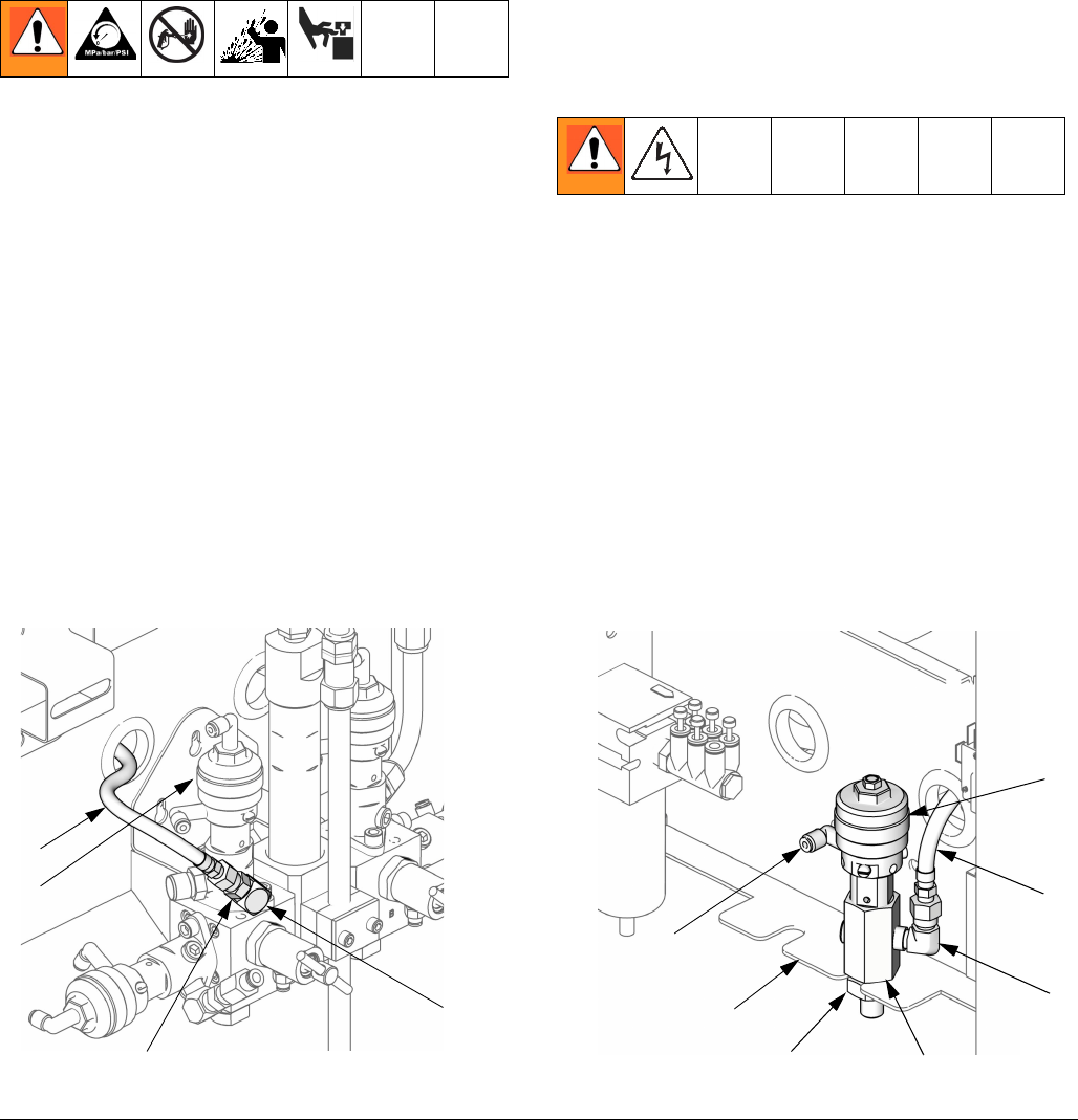
4. See F
IG
. 1. Remove the plug from the dose valve
adapter. Install the street elbow (18) in this port.
Install the nipple (19) in the elbow.
5. Install the dump valve assembly (includes 1, 2, 4,
and 11) in a slot of the flange (F) at the back of the
wall panel. Secure with the nut (8).
6. Install the elbow (6) in the open port of the dump
valve adapter (2). Connect a 1/4 npsm(f) hose (12)
between the elbow (6) and nipple (19).
7. Shut off all power to the fluid panel. Open the fluid
panel. See the Wall Panel detail in F
IG
. 2. Install the
solenoid (9) at the correct position (Dump Valve A
or Dump Valve B) on the solenoid manifold. Con-
nect the solenoid wires to the fluid panel control
board as shown in F
IG
. 3. Also see the System
Electrical Schematic on page 13.
8. Connect the tubing (7) between the solenoid mani-
fold and the tube fitting (T) on the dump valve (1).
See System Pneumatic Schematic, page 10.
F
IG
. 1: 15V821 Kit Installation
TI12744a TI12743a
At Back of Wall Panel
At Front of Wall Panel
1
V
18
6
8
F
T
2
12
12
A SIDE B SIDE
19


