


4
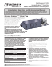
Grease Grabber Triple Play Kitchen Exhaust Pollution Control System
Installation
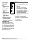
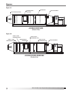
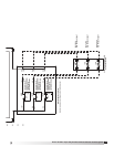
Rigging/Placing Equipment (See Figure #1)
1. The unit is furnished with lifting lugs at the four
corners and along the length as necessary.
2. Lift into place using all the lifting lugs.
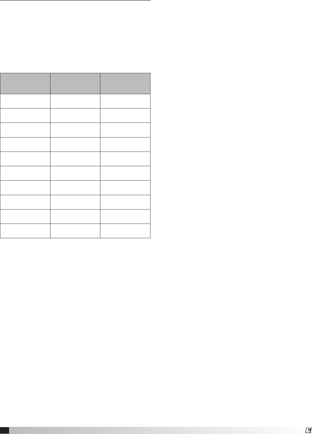
3. Field weight will vary depending upon final
selections such as fan type, accessories, etc.
Approximate weights are shown in the table
below.
4. The unit can be positioned on a base or curb
suitable for this purpose.
5. The unit must be anchored to its base/curb.
6. Alternatively, the unit may be suspended from
an adequate overhead structure, using suitable
undercarriage or hanging rods (by others). If the
unit is suspended by hanging rods, minimum
1/2 inch (12.7 mm) diameter threaded rod is to
be used. All hanger brackets/lifting lugs must be
used to ensure proper support of the unit. The
unit must also be hung level to ensure proper
operation.
7. A service clearance of 36 inches must be
provided on the access door side of the unit.
8. A minimum 18-inch clearance must be
maintained between this unit and any
combustible material.
9. The remote Filter Status Indicator (See Page
6) should be located in an area convenient for
monitoring by the cook staff. For details on wiring
this item, refer to the Electrical Connections
section on this page.
Duct Connections
Ductwork must conform to the IMC and SMACNA
guidelines.
As specified in NFPA 96, Ch. 7.5 (latest edition),
exhaust duct systems must be constructed in the
following manner; unless otherwise specified by the
local authority having jurisdiction (AHJ):
Materials
Ducts shall be constructed of and supported by
carbon steel not less than 1.37 mm (0.054 in.) (No. 16
MSG) in thickness or stainless steel not less than
1.09 mm (0.043 in.) (No. 18 MSG) in thickness.
Installation
All seams, joints, penetrations, and duct to hood collar
connections shall have a liquid-tight external weld.
An inlet transition is furnished to match the inlet duct
size. The inlet transition is furnished with a listed duct
access door for inspection and cleaning.
Units intended for indoor mounting are provided with a
UL 762 listed exhaust fan with outlet mounting flange.
Outlet ductwork from the exhaust fan is required to be
per the above mentioned methods unless otherwise
specified by the local authority having jurisdiction
(AHJ).
Electrical Connections
Electrical wiring must conform to the equipment data
plate information and to the NEC and local code
requirements.
Motor
This unit is furnished with a remote-mounted motor
starter and an ON/OFF disconnect switch mounted
adjacent to the fan and factory-wired to the fan motor.
A 3-phase electrical supply must be field wired to the
motor starter and from the motor starter to the ON/
OFF disconnect switch.
Refer to the applicable fan installation manual for
detailed instructions on wiring the fan.
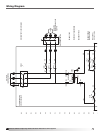
Remote Status Indicator
A single phase electrical supply must be field wired to
the pressure switch enclosure (located on the access
side of the Triple Play housing between filter stages 2
and 3, adjacent to the exhaust fan). For wiring details,
refer to the diagram on pages 8 and 9.
Unit Size
Approximate
Weight (lbs)
Approximate
Weight (kg)
10-10 1100 500
10-20 1600 727
10-30 2150 977
20-20 2600 1182
20-30 3500 1591
20-40 4200 1909
30-30 4700 2136
30-40 5700 2591
40-40 7300 3318
40-50 8000 3636