


4
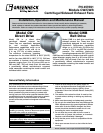
Model CW/CWB • Centrifugal Sidewall Exhaust Fans
®
G
H
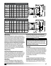
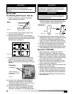
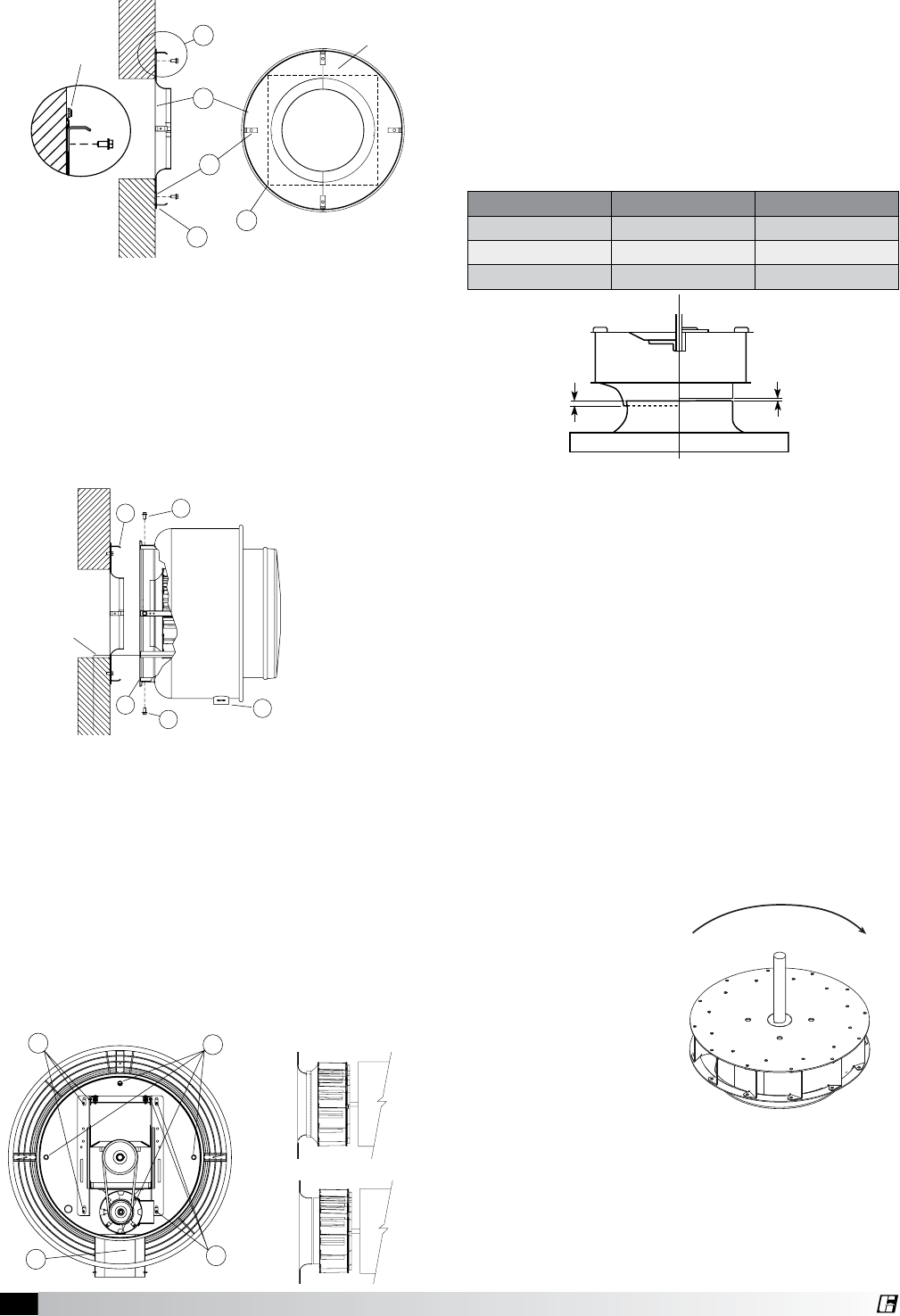
Wheel Overlap and Gap Dimensions
Model G - Overlap in (mm) H - Gap in (mm)
060-095 – 3/32
(2)
098-161 1/4 (6) –
180-300 1/2
(13) –
Figure 7
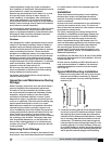
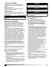
Wheel Rotation
All CW and CWB models
have clockwise rotation
when viewed from top
of fan
Figure 8
Clockwise
Airflow
Counterclockwise
Airflow
DETAIL
DETAIL
DECAL
TOP
Caulking
6
3
5
6
4
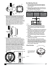
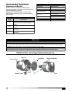
3. Once the mounting plate has been attached to the
wall, the unit can be installed. The unit should be
aligned with the breather tube (7) pointing down.
The electrical chase should be guided through the
hole in the motor compartment. The horizontal
support channels (8) should slide over the mounting
angle clips (10) on the mounting plate until the holes
in the windband and clips are aligned. Replace
fasteners (9) and tighten. Wiring now can be done.
Consult local code authorities for your specific
requirements.
4. During shipping, wheel position may shift.
Alignment should be as shown above (centered in
the inlet) and can be accomplished by loosening the
fasteners (11) located in the motor compartment.
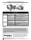
For belt drive units, additional vertical alignment can
be accomplished by loosening the four fasteners on
the drive frame support angles, and the 2 fasteners
that hold the L-brackets to the support angles on
top (13). Also, horizontal alignment can be made by
loosening the bearings from the bearing plate.
Removal of the entire power pack (motor, drives
and wheel) for maintenance or cleaning can be
accomplished by removing the breather tube (12) and
fasteners (11).
Pre-Starting Checks
1. Check all fasteners and setscrews for tightness.
The wheel should rotate freely and be aligned as
shown in gure 7.
2. Wheel position is preset and the unit is test run at
the factory. Movement may occur during shipment
and realignment may be necessary.
3. Only CW unit - Centering height alignment can
be accomplished by loosening the set screws in
the wheel and moving the wheel to the desired
position.
4. Only CWB unit - Centering can be accomplished by
loosening the bolts holding the drive frame to the
shock mounts and repositioning the drive frame.
5. Only CWB unit - Wheel and inlet cone overlap
can be adjusted by loosening the setscrews in
the wheel and moving the wheel to the desired
position.
6. Only CWB unit - Fan RPM should be checked and
veried with a tachometer.
7. Check wheel rotation (viewing from the shaft
side) by momentarily energizing the unit. Rotation
should be clockwise and correspond to the rotation
decal on the unit, see gure 8. If wheel rotation is
incorrect reverse two of the wiring leads or check
motor wiring for single phase.
9
8
9
7
ELECTRICAL
WIRING
10
11
12
13
13
CW/CWB Models 098 - 300
CW Models 060-095