


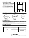
2 in.
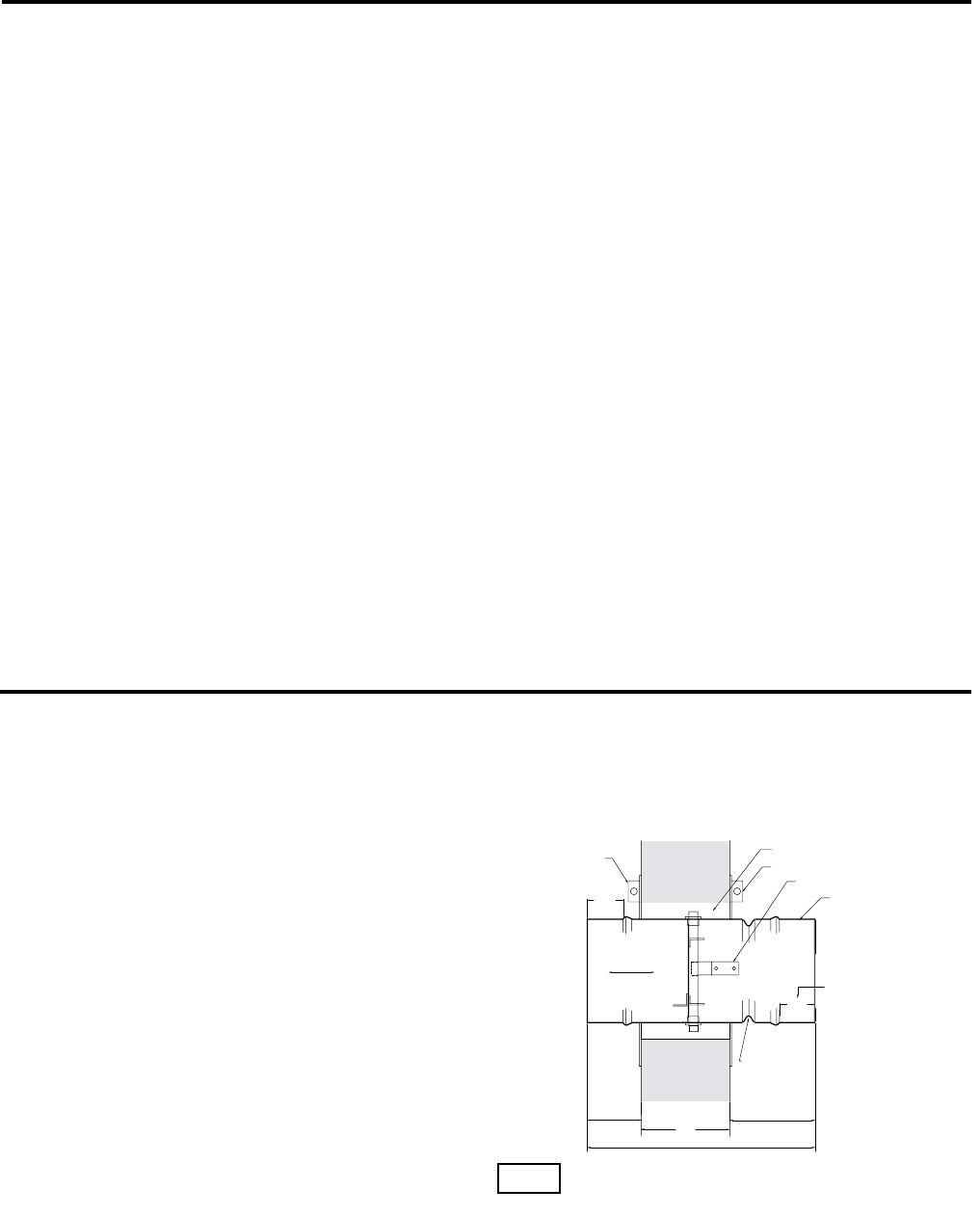
TW
AIRFLOW
SLEEVE LENGTH
2 in.
6 in. max.6 in. max.
(OPTIONAL)
RETAINER PLATE
DUCT CONNECTION
AREA
CLEARANCE FOR
EXPANSION
RETAINER PLATE
BLADE LATCH
ACCESS DOOR TO BE ON
SAME SIDE AS BLADE LATCH
DUCT CONNECTION
AREA
DO NOT PLACE RETAINER
PLATE IN THIS GROOVE
2
Pre-Installation Guidelines
The basic intent of a proper installation is to secure the fire damper in the opening in such a manner as to prevent
distortion and disruption of damper operation. This is accomplished by allowing the fire damper in rated separation
openings to expand and for the connecting duct to separate in the event of the collapse of the hanging system. The
following items will aid in completing the damper installation in a timely and effective manner.
1) Check the schedules for proper damper locations within the building. Visually inspect the damper for damage and
verify that the fusible link is in place or has not separated. Dampers will be supplied with a temperature responsive
fusible link device. If fusible link is not present or has separated, replace link. Never install a fire damper without the
proper UL approved fusible link in place.
2) Lift or handle damper using the frame. Do not lift damper using blades.
3) Do not install screws into the main body area of the damper frame as screws may interfere with and prevent damper
blade from opening and/or closing.
4) Damper must be installed into duct or opening free of distortion or other misalignment. Damper must not be
squeezed or stretched into duct or opening. Out of round, racked, twisted or misaligned installations can cause
torque requirements to exceed damper design.
5) Damper must be kept clean and protected from dirt, dust and other foreign materials prior to and after installation.
Examples of such foreign materials include but are not limited to: 1) Mortar dust 2) Drywall dust 3) Firesafing
materials 4) Wall texture and 5) Paint overspray.
6) Damper should be sufficiently covered to prevent overspray if wall texturing or spray painting will be performed
within 5 feet of the damper. Excessive dirt or foreign material deposits on damper can cause torque requirements to
exceed damper design.
7) Caulking is not allowed between the damper sleeve and the wall or floor opening (annular space). However, caulking
may be applied to the retaining plates and a field-applied sealant may be required for the damper sleeve and
transitions to meet certain duct leakage standards.
8) ACCESS: Suitable access (such that fusible links can be maintained) must be provided for damper inspection
and servicing. Where it is not possible to achieve sufficient size access, it will be necessary to install a removable
section of duct. (Refer to NFPA 90A).
9) The Code Authority Having Jurisdiction (AHJ) must evaluate and provide approval of final installation where
variations to these instructions are necessary.
Table of Contents
Pre-Installation Guidelines ...................................................................................2
Installation .........................................................................................................2-4
Maintenance .........................................................................................................4
Troubleshooting ....................................................................................................4
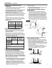
1. CLEARANCES REQUIRED BETWEEN FIRE
DAMPER SLEEVES AND WALL/FLOOR
OPENINGS
Fire damper assemblies expand during periods of
intense heat. Therefore, it is essential that openings in
walls or floors be larger than the fire damper assembly
to allow for this expansion. The wall/floor opening
must be a minimum of
7
/8 in. (22mm) larger than the
outside diameter of the damper. Refer to Section 4 for
additional installation considerations.
Fig. 1
These instructions apply to 1
1
/2 hour rated fire dampers mounted (blades must be horizontal) in: 1) masonry, block or stud
walls and 2) concrete floors or ceilings. Specific requirements in these instructions are mandatory. Dampers must be installed
in accordance with these instructions to meet the requirements of UL 555. The installation of the damper and all duct
connections to the damper sleeve shall conform to the latest editions of NFPA 90A, Standard for the Installation of Air
Conditioning and Ventilating Systems, and the SMACNA Fire, Smoke and Radiation Damper Installation Guide, and UL
Classifications R13317.
Installation - Failure to follow these instructions will void all warranties.