


12
Typical Installations
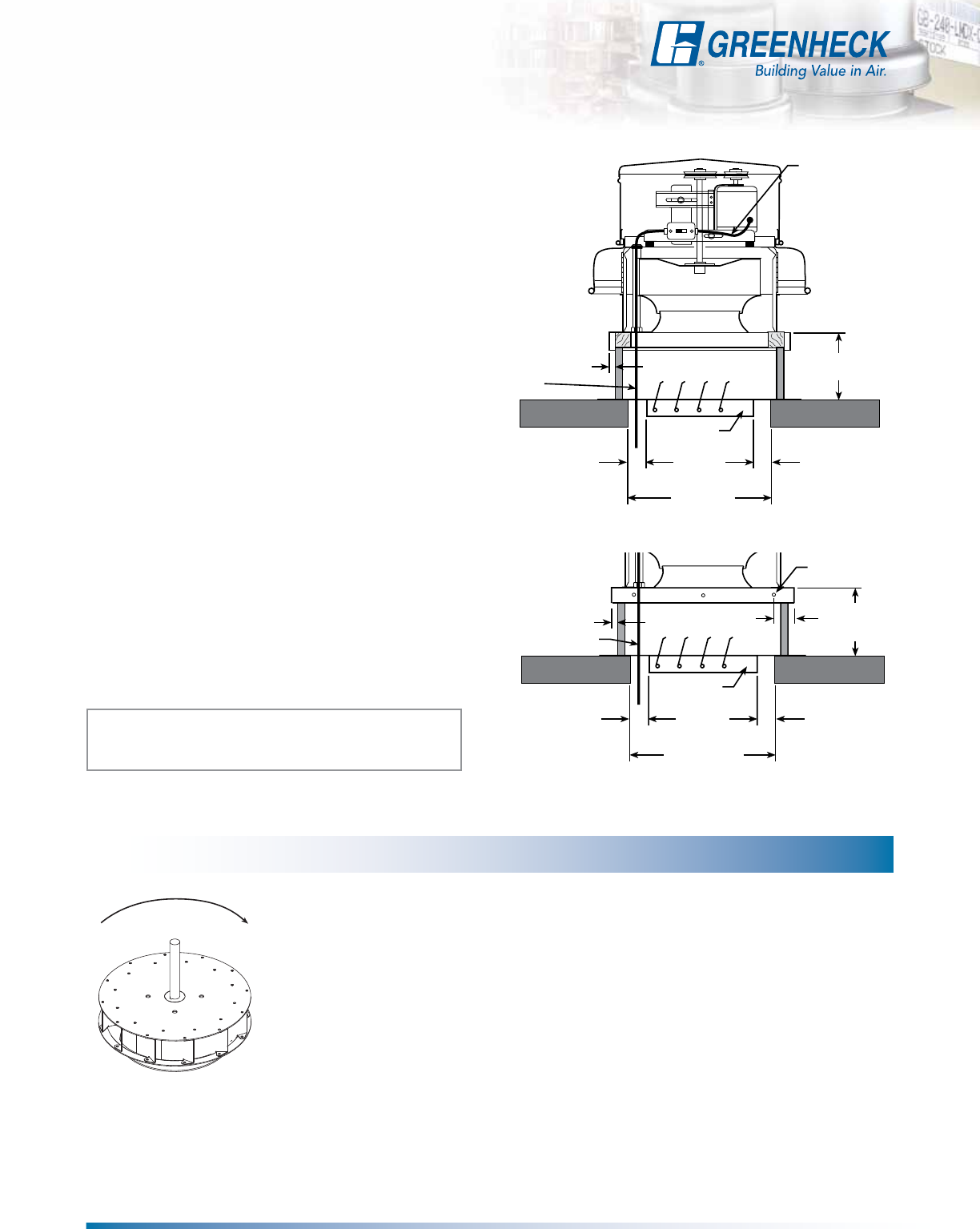
Models G and GB
Note: The typical installations shown are recommendations
based on national codes. Local authority may supersede these
recommendations.
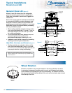
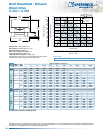
General Clean Air (figure 1)
Models G and GB exhaust fans are designed to
meet the needs of general clean air applications.
Tests were conducted to assure safe, rugged and
reliable fans.
Due to the varying types of airstreams encountered
in commercial ventilation, system designers must
be aware of national, state, and local codes and
guidelines governing these installations. Local code
authorities should be consulted before proceeding
with any ventilation project.
• When roofing materials extend to the top of the
curb, roof curbs should be 1
1
⁄2 inches (
3
⁄4 inch on
each side) less than the unit curb cap to allow
for roofing and flashing.
• For recommended duct size, damper size, and
roof opening dimensions, refer to the
performance data pages. (starting on t. 14)
• Installation must include a means for inspecting,
cleaning and servicing the exhaust fan.
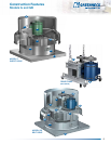
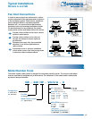
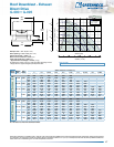
High Wind, Hurricane and Seismic (figure 2)
• Roofing materials can extend to the top of the
curb, roof curbs should be 1 inch (25 mm) total,
or
1
⁄2inch (13 mm) on each side, less than the unit
curb cap to allow for roofing and flashing.
Recommended
Duct and
Damper Size
Recommended
Roof Opening
1
1
/4 in.
(32 mm)
3/4 in.
(19 mm)
Factory Wired
from Motor to
Disconnect
Wiring by
Others
8 or 12 in.
(203 or 305 mm)
Damper
1
1
/4 in.
(32 mm)
Recommended
Duct and
Damper Size
Recommended
Roof Opening
1
1
/4 in. (32 mm)
1/2 in. (13 mm)
Factory Wired
from Motor to
Disconnect
Wiring by
Others
8 - 24 in.
(203 - 610 mm)
GPF or SD Curb
Damper
1
1
/4 in. (32 mm)
1/4 in. (6 mm)
Fastener
4 in. (102 mm)
From Curb Edge
Wheel Rotation
Direction of rotation is very critical. Rotation in the wrong direction will result
in excessive horsepower, possible motor burnout, and increased noise levels.
Check rotation by energizing the unit only momentarily. The rotation should be
the same as the rotation decals afxed to the unit and is clockwise when viewed
from the top of the unit.
Clockwise
Airflow
Counterclockwise
Airflow
figure 1
figure 2