


4
Sidewall Propeller Fans • Exhaust, Supply and Filtered Supply
®
Typical Installation
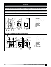
Move fan to the desired location and determine the
method by which the fan is to be mounted as shown
in Figures 1-4 shown on page 3. Optional wall mount
housings (Figure 1) and wall mount collars (Figure
2) provide a convenient means of mounting sidewall
propeller fans while maintaining the proper distance
between propeller and damper.
Attach the fan by inserting a suitable fastener
through each of the prepunched mounting holes in
the fan panel. Care should be taken not to bend or
distort the fan panel or drive components during
installation.
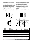
Support Braces
Wall Housing sizes 42 and larger with heavy motors
and all Filtered Supply Wall Housings need additional
bracing.
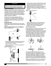
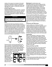
Filtered Supply Wall Housing Installation
Step 1 Install Housing
Install housing through wall opening from outside.
Temporarily brace end of unit until permanent
support braces are installed.
Secure through prepunched holes in angles with
suitable fasteners.
Step 2 Install Support Braces
Choose method of support. Attach support to end
of unit (above or below housing) with rods, cable,
angle, etc. (supplied by others) as shown.
Vertical braces must carry a minimum load of 500
pounds per support, and angled (45 °) braces a
minimum of 750 pounds per support based on two
supports.
Step 3 Install Weatherhood
Position weatherhood over end of wall housing
and fasten through mounting holes with self-
tapping screws. Caulk, flash and complete
electrical hook-up to finish installation.
Pre-Starting Checks
Check all fasteners and setscrews for tightness. This
is especially important for bearing setscrews.
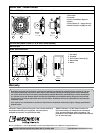
The propeller should rotate freely and not rub on the
fan panel venturi. Rotation direction of the propeller
should be checked by momentarily turning the unit
on. Propeller blade should cup and throw the air
when rotating in the correct rotation as shown in
the figure below. Rotation should be in the same
direction as the rotation decal affixed to the unit.
For 3-phase installations, fan rotation can be
reversed by simply interchanging any two of the
three electrical leads. For single-phase installations
follow the wiring diagram located on the motor.
For Belt Drive Fans: The adjustable motor pulley is
preset at the factory for the specified fan RPM. Fan
speed can be increased by closing or decreased by
opening the adjustable pulley. Two or three groove
variable pitch pulleys must be adjusted an equal
INTERIOR EXTERIOR
Wall
Airflow
Mounting
Angles
Temporary
Brace
Wall
500 lb. load
per support
500 lb. load
per support
750 lb. load
per support
750 lb. load
per support
45º
45º
WallWall
Optional 90º
Weatherhood
WallWall
INTERIOR EXTERIOR
Wall
Airflow
Mounting
Angles
Temporary
Brace
Wall
500 lb. load
per support
500 lb. load
per support
750 lb. load
per support
750 lb. load
per support
45º
45º
WallWall
Optional 90º
Weatherhood
WallWall
INTERIOR EXTERIOR
Wall
Airflow
Mounting
Angles
Temporary
Brace
Wall
500 lb. load
per support
500 lb. load
per support
750 lb. load
per support
750 lb. load
per support
45º
45º
WallWall
Optional 90º
Weatherhood
WallWall
WARNING
Always disconnect, lock and tag power source before
installing or servicing. Failure to disconnect power
source can result in fire, shock or serious injury.