


5
Model SQ/BSQ • Centrifugal Inline Exhaust Fans
®
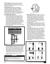
Duct Length: The inlet and outlet duct length
should be approximately two to three wheel
diameters long before and after the fan to achieve
cataloged performance.
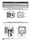
Side Discharge: Make sure discharge is
orientated in the same direction as originally
ordered, performance will change with different
discharge positions. Refer to Figure 12 for
proper side discharge definition and chart 4 for
dimensions, page 4. Refer to the CAPS program or
consult factory for performance corrections.
Pre Start-Up Checks
1. Check all fasteners for tightness. The wheel
should rotate freely and be aligned as shown
in Figure 13. Wheel position is preset and the
unit is tested at the factory. Movement may
occur during shipment, and realignment may
be necessary. Centering can be accomplished
by loosening the bolts holding the inlet (venturi)
panel and repositioning. Wheel and inlet cone
overlap can be adjusted by loosening the
setscrews in the wheel and moving the wheel to
the desired position.
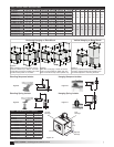
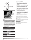
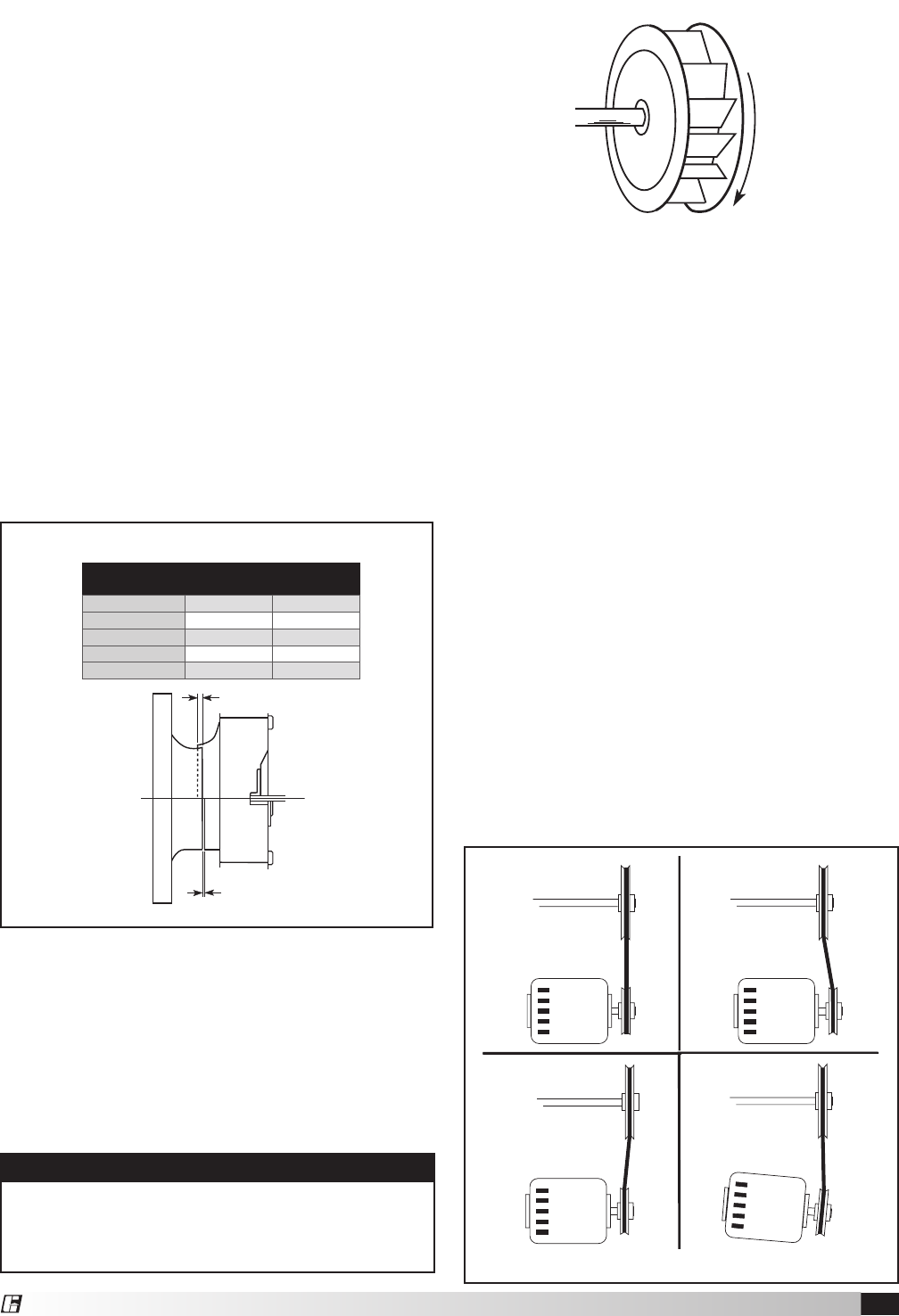
2. Wheel Rotation: Direction of wheel rotation
is critical. Reversed rotation will result in poor air
performance, motor overloading and possible
burnout. Check wheel rotation by momentarily
energizing the unit (all SQ and BSQ fans have
clockwise wheel rotation when viewed from top
of fan). Rotation should be clockwise as shown
in Figure 14 and correspond to the rotation
decal on the unit.
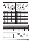
3. Vibration Isolators: After fan is moved to
desired location, punch out the four knock-out
holes which are located on the unit top and
bottom panels. Assemble the brackets to the
unit according to the appropriate drawings
on page 4 and refer to respective parts list on
page 11. Make certain all connectors are tight
and that all washers are in.
4. For BSQ Fans: If adjustments are made, it is
very important to check the pulleys for proper
alignment. Misaligned pulleys lead to excessive
belt wear, vibration, noise, and power loss. (see
Figure 15).
5. For BSQ Fans: Belt tension can be adjusted
by loosening four fasteners marked “R” on
the drive frame. (refer to Figure 17 on page 6).
The motor plate slides on the slotted adjusting
arms. Belt tension should be adjusted to allow
1/64 inch of deflection per inch of belt span.
For example, a 15 inch belt span should have
15/64 inch (or about 1/4 inch) of deflection with
moderate thumb pressure at mid-point between
pulleys (see Figure 16). Overtightening will
cause excessive bearing wear and noise. Too
little tension will cause slippage at start-up and
uneven wear.
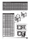
Wheel Overlap Dimensions
Figure 13
Model
G - Overlap
in. (mm)
H - Gap
in. (mm)
SQ 60-95
-
1/8 (3)
SQ 100-160 1/4 (6)
-
BSQ 70-160 1/4 (6) -
BSQ 180-240 3/8 (10)
-
BSQ 300-420 1/2 (13)
-
G
H
C
l
o
c
k
w
i
s
e
Figure 14
Figure 15
Belt Span
Deflection =
Belt Span
64
WRONGWRONGWRONGCORRECT
G
C
l
o
c
k
w
i
s
e
Belt Span
Deflection =
Belt Span
64
WRONGWRONGWRONGCORRECT
G
C
l
o
c
k
w
i
s
e
Belt Span
Deflection =
Belt Span
64
WRONGWRONGWRONGCORRECT
G
C
l
o
c
k
w
i
s
e
WARNING
Correct direction of wheel rotation is critical.
Reversed rotation will result in poor air
performance, motor overloading and possible
burnout.