


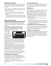
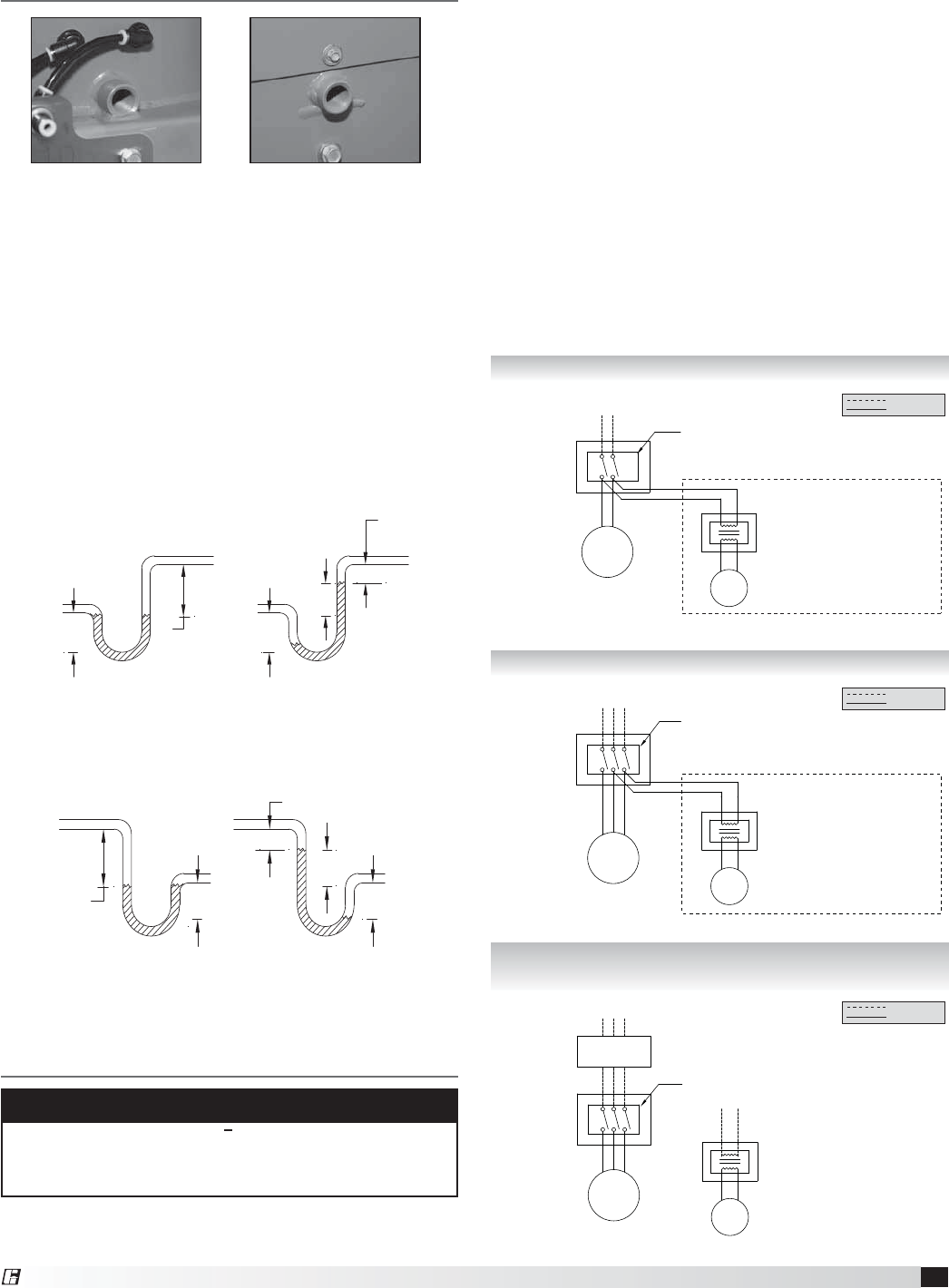
Plenum Drainage Piping / Trap
Detail (By Others)
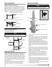
There is a location for a pipe connection on each tubular
fan housing and bypass air plenum. Each drain may
need to be connected to a drainage system to ensure
proper disposal of any water or condensate that may
occur.
t %SBJODPOOFDUJPOTBSFJODI/15
t *OTUBMMFEQJQJOHUPIBWFBEPXOXBSEBOHMFUPBMMPX
for drainage
t 'JMMUSBQTUPSFDPNNFOEFEMFWFMCFGPSFTUBSUVQ
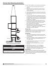
Note: A conservative method of trap design is to set N
= total static pressure.
Positive Pressure Trap on Tubular Fan Housing
Fan Drain
Connection
Plenum Drain
Connection
Negative Pressure Trap on Bypass Air Plenum
N = Negative fan pressure (inches W.C.)
H = N - (0.5 inches minimum
H/2
H/2
H
1.25 inch minimum
N
FAN ON
FAN OFF
N = Negative fan pressure (inches W.C.)
H = N - (0.5 inches minimum)
H/2 H/2
H
1.25 inch
minimum
N
FAN ONFAN OFF
Connect
this end
to fan drain.
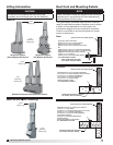
Before electrical connections are made, the supply
voltage, phase and ampere capacity must be checked
Electrical Connections
NOTE
Refer to the Vektor-HS SAVVE controls
Installation, Operation and Maintenance Manual
for electrical wiring and connection information.
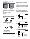
Single Phase Layout
LINE IN
115/208/230/277 volt, single phase
MOTOR
DISCONNECT
115/208/230/277 volt
Single phase
TRANSFORMER
208/230/277 volt, single phase
Transformers must be wired independent
from VFD control.
24/115 volt, single phase
isolation damper actuator motor
power open/spring close
115/208/230/277 volt
Single phase
Disconnect is mounted to fan housing
Optional transformer and isolation damper, refer to CAPS file selection
Field Wiring
Factory Wiring
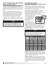
Three Phase Layout
LINE IN
208/230/460/575 volt, three phase
MOTOR
DISCONNECT
208/230/460/575 volt
Three phase
TRANSFORMER
208/230/460/575 volt, single phase
Transformers must be wired independent
from VFD control.
24/115 volt, single phase
isolation damper actuator motor
power open/spring close
208/230/460/575 volt
60 cycle, three phase
Disconnect is mounted to fan housing
Optional transformer and isolation damper, refer to CAPS file selection
Field Wiring
Factory Wiring
Three Phase with
Variable Frequency Drives Layout
LINE IN
208/230/460/575 volt, three phase
MOTOR
DISCONNECT
208/230/460/575 volt
Three phase
VFD
supplied and wired
by others
TRANSFORMER (if required)
208/230/460/575 volt, single phase
Transformers must be wired independent
from VFD control.
24/115 volt, single phase
isolation damper actuator motor
power open/spring close
208/230/460/575 volt
60 cycle, three phase
Disconnect is mounted to fan housing
Optional transformer and isolation damper,
refer to CAPS file selection
Field Wiring
Factory Wiring
for compatibility with the fan motor. In addition, the
supply wiring must be properly fused and conform to
local and national electrical codes. If the unit is supplied
with a safety disconnect switch, ensure proper wiring
to the fan motor. Be sure the disconnect is switched to
the “OFF” position before connecting supply wires. If
no disconnect is supplied, ensure the supply wire is not
live before connection. Supply wires are then connected
to the optional safety disconnect switch (if supplied) or
motor.
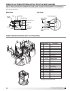
Vektor-H Motor Disconnect and Isolation Damper
Wiring Diagram
Disconnect is mounted to fan housing. Transformers are
mounted to bypass air plenum with damper actuator
motors. For systems that ship unassembled because
of physical size, this connection at disconnect from
transformers must be field-installed. Wires with conduit
and fittings are provided pre-connected to transformers.
7
Laboratory Exhaust System
®