


Replacing Water Tank on Machines with Serial # 339304 and Lower: (cont.)
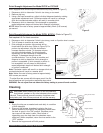
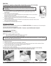
4. Disconnect dump valve wiring and tubing in left access opening and remove valves.
5. Disconnect tank fill tubing from inlet valve in rear of unit.
6. Remove screws holding water tank and
mounting bracket. Remove tank,
bracket and old tubing
(NOTE: Do not discard dump valve
tubing).
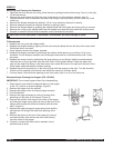
7. Remove heating element, thermal
probe, water probe, vent fittings, and
valve retaining clip from old tank.
Examine to determine if these items
need to be replaced. Remove and
discard old hi-level thermostat and
mounting bracket.
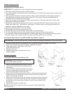
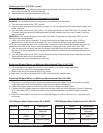
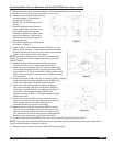
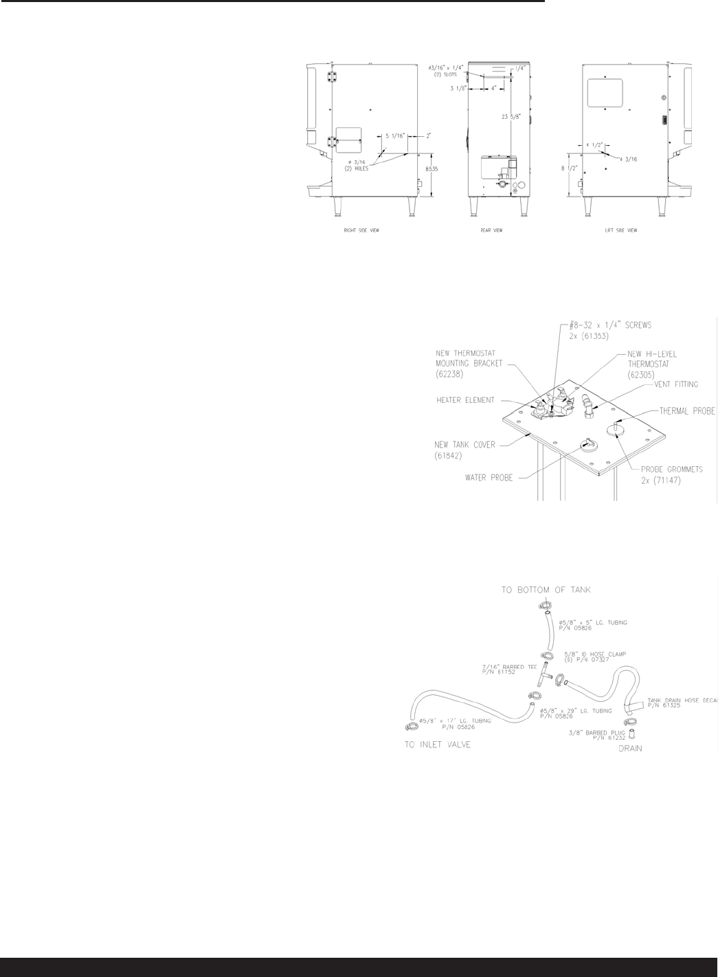
8. Drill holes in cabinet per sketch below
and deburr. (Figure Y)
9. Install (3) #8-32 x 3/8" machine screws (07026-07) in new
holes in sides of casing. Lower new tank retaining bracket
(61845) from the top of the unit until it rests on the machine
screws. Add locknuts (71261) and tighten.
NOTE: Instructions above are for units with a stainless steel
casing, for units with a black powder coat casing, use black
screws (61303).
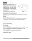
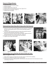
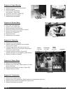
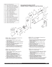
10. Install new dump-valve grommets (61243) and plugs
(61229) (for PIC2 only) in side of new tank (61841).
11. Install new probe grommets (71147), heating element with
new hi-level thermostat (62305), mounting bracket (62238)
and (2) #8-32 x ¼" SS screws (61353), thermal probe, water
probe, and vent fittings in new tank cover (61842) as shown
in sketch below.
12. Place tank gasket (61844) over top of new tank (61841), aligning
holes with studs, and lower new tank cover (61842) over
studs. Bolt tightly with (10) #8-32 locknuts (71261).
13. Lower tank onto retaining bracket, feeding fill fitting in
tank bottom through the hole in the bracket. Bolt tank
to the back of casing with (2) lock washers (61186) and
(2) #8-32 x 3/8" machine screws (07026-07) for
stainless casings, or #8-32 x 3/8" black screws for black
powder coat units.
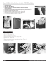
14. Install new o-rings (61365) on dump valves and insert
them into side of tank from the access panel in the side
of the casing. Secure with valve retaining clip,
reconnect all wires and dump valve tubing.
15. Measure and cut new 29" vent tubing (05826), connect
one end to the vent fitting in the top of tank and run the
other end down the side of the tank to the bottom of the
unit. Reconnect all wires to tank ground, heating element,
thermal probe, water probe, and hi-level thermostat.
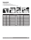
16. Cut and install new tubing (05826) from inlet valve to tank fill fitting and drain per sketch.
NOTE: Apply tank drain hose decal (61325) to drain hose after installing and feeding drain hose through hole in
control mounting bracket in bottom of the unit.
17. Replace all panels and reconnect to water and electrical supply.
Figure Z
Figure AA
Crathco® Powdered Beverage Dispensers Page 15
Figure Y