Model T10699 (Mfg. Since 2/13)
-3-
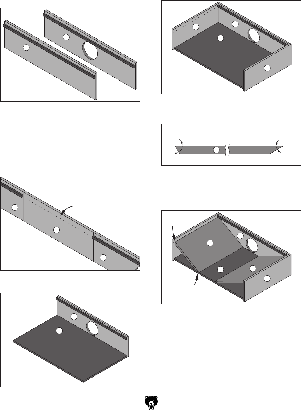
5. Attach Guide Bars (F) to Front Piece (B) and
Rear Piece (C) with top edges along the lines
you marked in the previous step.
C
B
7. Attach Rear Piece (C) to Bottom Piece (A).
C
A
6. Position one Side Piece (D) between Front
Piece (B) and Rear Piece (C), then place
a straightedge against the bottom of Guide
Bars (F) and mark a line across Side Piece
(D). Repeat with the other Side Piece (D).
These lines will help you position Inserts (E)
during a later step.
B
D
C
Line Indicating
Bottom Edge
of Guide Bars
8. Attach Side Pieces (D) to Bottom Piece (A)
and Rear Piece (C).
D
C
A
D
10. Place the 60° ends of Inserts (E) just below
the lines on Side Pieces (D), then attach
Inserts (E) to Side Pieces (D) and Bottom
Piece (A).
D
C
A
E
E
D
60°
30°
9. Miter cut one end of Inserts (E) at 60° and the
other end at 30°.
E
60° 30°


