


PNEG-524 Roof Exhaust Fan 19
7. ELECTRICAL INSTALLATION
Fan Disconnect
A disconnect for the fan needs to be sized to handle the recommended fusetron size.
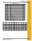
Example: For a 24" fan the first chart on Page 17 would be used, and the fusetron size is 30
AMP. Install the fusetron recommended in the disconnect. A circuit breaker can be used,
however, the circuit breaker or any fuse used must be a time delay type to allow the initial starting
inrush current to the fan.
Conductor Size for the Fan Disconnect to Fan Wiring
The conductor size for the fan needs to be sized according to the distance between the fan and
disconnect. Example: For a 24" fan located 200' from the disconnect use the first chart
on Page 17 to determine the conductor size to be a 14 AWG. The proper size wiring must be
used to make sure a voltage drop does not occur.
Fan Motor Controller
Size the fan motor controller according to the motor ratings for a convenient control location as
follows:
Motors with internal overload protection will require a magnetic contactor to control fan
operation. Motors without overload protection will require a magnetic starter with overload
protection to control fan operation.
Single Phase
A 3-wire system should be provided for fans to be operated on single phase power. The three
wires consist of the two current conductors and a ground. The current carrying conductors are
wired per the diagram on the motor. The ground is secured to the motor frame. On 2 HP
explosion proof motors thermostat wires are provided with the motor, and must be connected to
the fan motor magnetic controls.
Three Phase
A 4-wire system should be provided for fans to be operated on three phase power. The four wires
consist of three current carrying conductors, and a ground. The current carrying conductors are
wired per the diagram on the motor. The ground is secured to the motor frame. On 2 HP
explosion proof motors thermostat wires are provided with the motor, and must be connected to
the fan motor magnetic controls.
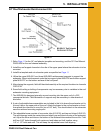
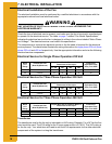
When installing electrical service for explosion proof motors make sure all conduit and
connectors exposed to the conditions of the motor are rated for the Class II group F and G
location of the motor.
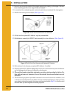
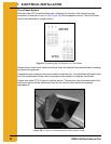
Installation Check
When the fan is completely assembled and wired the unit needs to be checked for proper
rotation. Provide power to the fan controls and start the fan momentarily. Make sure the fan blade
rotates to exhaust air from the bin. If the blade is rotating the wrong direction, have your
electrician correct as follows:
Single Phase System
With the power OFF at the fan disconnect, the motor lead wires at the fan motor need to change
as indicated on the motor to reverse the blade rotation. The unit then needs to be rechecked for
proper rotation.