


10
installation instructions.
4. Multiple venting should be
avoided wherever possible. Never
install your stove into the same vent
as a gas furnace.
5. Check for proper roof clear-
ances. See page 5 and check your
local codes.
6. Chimney must be two feet high-
er than anything ten feet around it.
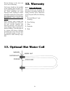
D. Flue Pipe
1. Chimney should be within 8 feet
of the stove.
2. No more than two 90 degree
elbows should be used.
E. Check for Proper Draft
The chimney used must be capable
of providing a minimum of .06 inch-
es water column draft.
F. A Barometric Draft Regulator
May be used and set at .06 to .10
inches water column.
Safety and Service Clearances -
Regardless if you use your stove as a
separate independent stove installa-
tion or in the parallel configuration
with another furnace, the following
steps will apply in your decision as
to where and how you will install
your new solid fuel stove.
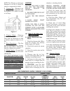
Clearance to Combustibles
Models SF-150, SF-250
Safe stove clearance to combustible
walls is 24" to rear and 36" to sides
and front. Floor protection for a
combustible floor should consist of
3/8" asbestos millboard or a stove
mat providing equal protection. The
floor protector should extend 8" to
either side and 16" in front of the
stove. Floor protection should also
extend 2" to either side of chimney
connector.
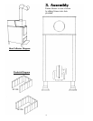
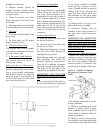
Leveling Adjustable Feet
A. Lean the stove back and screw
on the two front feet.
B. Lean the stove front and screw
on the two rear feet.
C. Make final adjustments to bring
the stove into a level position by
adjusting feet as required.
Most Harman stoves are equipped
with adjustable feet which are
adjusted simply by turning them.
They are 4" in diameter to support
the stove without marring the floor.
The shape of the foot adds to the
appearance and quality of the stove.
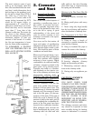
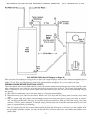
I M P O R TANT! THE FLUE PIPE
MUST BE 24 GAUGE OR THICK-
ER.
When connecting the flue pipe to
the stove the first section of the pipe
or the elbow should be installed
inside the flue connector on the
stove. It should be held in place by
drilling three holes through the
pipe. The holes should be of suit-
able diameter for the sheet metal
screws or pop rivets used for fasten-
ing.
A straight section of pipe or an
elbow must now be installed.
A barometric damper may be
installed on this vertical section of
the pipe. Use a listed barometric
damper.
IMPORTANT! ALL HORIZONTAL
RUNS SHOULD HAVE A 1/4"
RISE TO THE FOOT SO THAT
ANY LIQUID CREOSOTE THAT
MAY DEVELOP WILL RUN BACK
INTO THE STOVE.
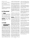
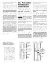
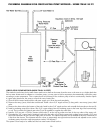
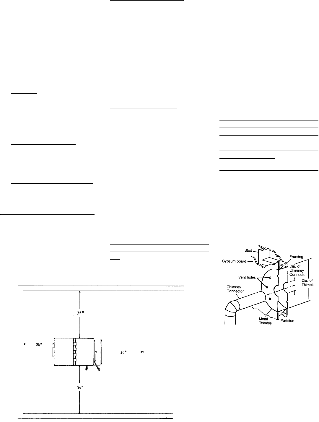
Connector thru Walls and Chimney
- NFPA 211 does not permit a
chimney connector to pass through
any floor or ceiling or through any
fire wall or fire partition. However,
where necessary, a connector may
pass through a partition other than
a fire partition under any of the fol-
lowing conditions:
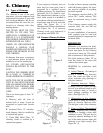
A. Where a ventilated type metal
thimble, as shown above is used.
Such a thimble must be at least 12
inches larger in diameter than the
chimney connector.
B. Where a metal or burned fire-
clay thimble is used and the thimble
is surrounded on all sides by not less
Figure 4. Thimble for Passing
Smokepipe (Connector) Thru
Walls