


16
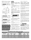
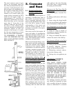
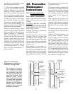
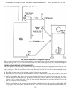
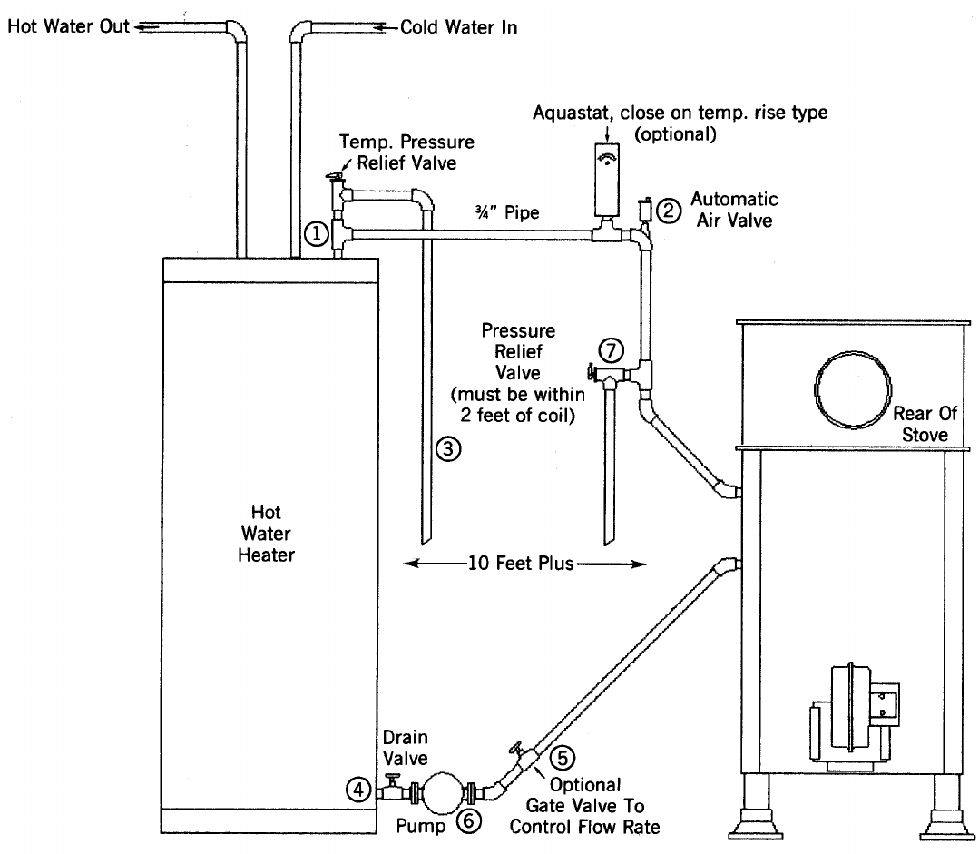
PLUMBING DIAGRAM FOR CIRCULATING PUMP METHOD - MORE THAN 10 FT.
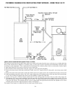
CIRCULATING PUMP METHOD (MORE THAN 10 FEET)
This method is used when the hot water heater tank is more than ten feet away from the stove or the stove is on a higher level than
the hot water heater tank. In addition to a circulator pump, you may want to add an aquastat to thermostatically control the pump
according to water temperature. This is optional and not necessary if the circulator pump is left run continuously. Another option
is a gate valve placed near the pump to control the rate of water flow.
a) Shut off the hot water heater and the old water supply to it. Drain the tank completely.
b) Remove the temp./press./relief valve and discard. Install a short 3/4" nipple and tee (1) along with a new temp./press./relief
valve.
c) Remove the drain valve at the bottom of the tank. Install a short 3/4" nipple and tee and re-install the drain valve to the tee (4).
d) Install a circulating pump (6) as shown. Run 3/4" copper tubing from the circulating pump to the lower leg of the heat exchang-
er coil. This is where the optional gate valve (5) can be installed to regulate the water flow.
e) Install a 3/4" tee and a 150 lbs. pressure relief valve (7) in the top leg within two feet of the top outlet of the water coil.
f) Complete the 3/4" copper line by running it back to the tee at the top of the hot water tank, making sure to install a 3/4" vent
elbow and automatic air vent (2) at the high point of the line. The optional aquastat can be installed in this line a maximum of
6 feet from the furnace. This aquastat must be a close on temperature rise type and must be wired and adjusted to turn on the
circulating pump when the water temperature reaches 120 degrees F.
The system is now ready to be refilled and the hot water heater turned back on.