


27
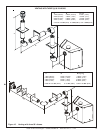
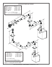
Hearth & Home Technologies • 6000BE, 6000BE-IPI • 2024-900 Rev. G • 11/05
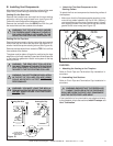
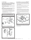
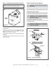
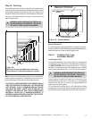
Step 5. Installing the Optional Heat-Zone Kit
NOTE: There must be NO INSULATION or other com-
bustibles inside the framed firestop opening.
HEAT-ZONE
ATTACHES
HERE
Figure 32.
1. Remove the knockout from the fireplace and discard it
(see Figure 32).
2. Center the duct collar around the exposed hole and at-
tach it to the fireplace with 3 screws. NOTE: Do this BE-
FORE final positioning of the fireplace.
3. Determine the location for the air register/fan housing
assembly.
Reference the Heat-Zone kit instructions for the remaining
installation steps.
!
!
!
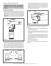
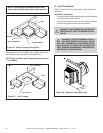
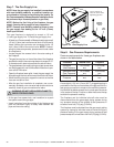
Step 6. The Gas Control Systems
WARNING: THIS UNIT IS NOT FOR USE WITH
SOLID FUEL.
Two types of gas control systems are used with these models:
Standing Pilot Ignition and Intermittent Pilot Ignition (IPI).
Standing Pilot Ignition System
This system includes millivolt control valve, standing pilot,
thermopile/thermocouple flame sensor, and piezo ignitor.
WARNING: 110-120 VAC MUST NEVER BE
CONNECTED TO A CONTROL VALVE IN A
MILLIVOLT SYSTEM.
Intermittent Pilot Ignition (IPI) System
This system includes a 3V control valve, electronic module
and intermittent pilot.
WARNING: CONTINUOUS 110-120 VAC SER-
VICE MUST BE WIRED DIRECTLY TO THE FIRE-
PLACE JUNCTION BOX.
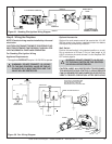
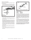
Figure 33. Gas Controls Systems
INTERMITTENT PILOT IGNITION
STANDING PILOT
FLAME SENSOR
ROD