


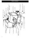


Boiler Kit Materials: (Refer to page 2)
List of items contained within the boiler kit shipped with
the unit.
1 - Control board cover
1 - Access cover (Hopper Swing Plate Knob)
5 - Spring Handles
1 - 1/2” Boiler Drain
1 - 3/4” Safety Relief Valve
1 - 1/2” Aquastat Well
1 - 1/2” Dual Temperature/Pressure Gauge
1 - 100ft. Sensor Cable (Outdoor Air Sensor)
1 - Outdoor Air Sensor
1 - Flue Tunnel Weldment
1 - Combustion Blower Assembly
1 - Heat Shield (Comb. Blower)
2 - UY Connectors
2 - Terminals 1/4 Female
1 - #8 X 1/2” TEK
3 - 1/4-20 X 5/8” Wing Screw
4 - 1/4” Lock Washer
4 - 1/4-20 Nuts
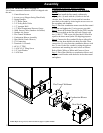
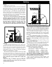
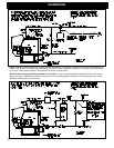
Installation of the Flue Tunnel Weldment,
Combustion Blower and Wiring, ESP and Heat
Shield:
Step 1: First install the ue tunnel weldment by
aligning the (4) studs with the (4) holes in the ash
chamber base. Fasten the (4) nuts and lock washers
provided, to the studs by removing the access cover on
the secondary ash chamber.
Step 2: Place the combustion motor onto the ue tunnel
weldment and tighten the (3) wing screws provided.
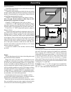
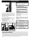
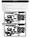
Step 3: Insert the Exhaust Sensing Probe (ESP) into the
1/8” hole provided on the ue pipe stub. Fasten with
the (1) #8x1/2” TEK screw also provided. ESP will be
taped to the sheet metal jacket for shipping purposes.
Step 4: Connect the ex conduit 90 degree elbow(Not
Shown) to the heat shield in the hole provided. Then
connect the (3) wires from the combustion blower with
the (3) wires in the ex conduit by using the push-on
connectors and matching the wire colors as follows:
Red to Black, White to White and Green to Green.
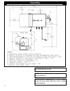
Step 5: Place Heat Shield over combustion blower and
align the swell latches with the holes in the sheet metal
and tighten.
NOTE: Refer to Fig’s 22, 23, and 24 located on page 31 of this manual.
Flue Tunnel Weldment
Heat Shield
ESP
Combustion Blower