


4
Installation Tips
• Use a minimum 18 gauge wire for all low voltage connections.
• The Beacon II board gets its 24 VAC power supply from a transformer mounted in the
electrical end of each evaporator. On 208-240 volt systems the multi-tap transformer is
shipped from our factory wired for 240 volts. If your supply voltage is 208 volt you must
change to the 208 volt tap on the transformer.
Note: On multiple evaporators, since a transformer is in each evaporator, the voltage
tap must be set on each evaporator.
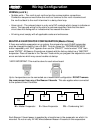
• Refer to wiring schematic shipped on units for unit wiring. Schematics in this Installation
& Operation Manual are typical wiring schematics only.
• Program ALL slave evaporators as SLAVES.
• Evaporators are shipped from our factory with a preset box setpoint temperature of 35°F
for air defrost and -10°F for electric defrost. If your box setpoint temperature
requirements are different this must be set using directions outlined under “Room
Temperature Control”.
• The suction line temperature sensor MUST be removed from the suction line before
brazing the suction tubing. The sensor MUST then be reinstalled on the suction line
after brazing is completed and the tubing has cooled. Insulate when finished.
• The low pressure switch time delay relay, located in the condensing unit, must be set to
1 minute.
• If electrical power will be connected prior to evacuation and charging of system, unplug
electric expansion valve from board until system is ready to be evacuated, leak tested
and charged.
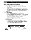
• Some systems may require the crankcase heater be energized 24 hours prior to start-
up. The Beacon should be de-energized for this period by placing it in the SERVICE
MODE. This is done by pressing the “FORCE SERVICE” button twice. To start the
system cooling, press the “CLEAR” button.
• Room sensors must be left connected on ALL evaporators.
• A pressure transducer is installed on the evaporator. Do not leak test system above 150
PSI or damage to transducer could occur. If leak testing must be greater than 150 psig,
disconnect the transducer from he suction header and reconnect after testing is
complete.
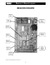
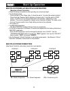
CONDENSING UNIT
The condensing unit control panel contains the relays, contactors, time delay and a
terminal block which is appropriately marked to match the low voltage wiring connections. A
sensor for outdoor air temperature measurement is installed on the condensing unit.
Condensing unit must be installed using proper refrigeration practices and codes. Make
sure there is sufficient clearances around unit for adequate air flow and access.
EVAPORATOR UNIT
The evaporator contains the Beacon II controller, electric expansion valve, pressure
transducer, distributor, orifice, transformer and three sensors. These components are all
factory mounted and wired. The three sensors are factory mounted and provide input to the
controller from the following: defrost temp., suction temp., room temp.
Each evaporator unit must be installed using proper refrigeration practices and codes.
Make sure the piping is correctly sized and properly routed. It is highly recommended that
the liquid and suction lines be insulated. There must also be good clearance around unit.
See Heatcraft Refrigeration Installation & Operation Manual for more details.
Installation