


6
1. Owner's Operating Instructions
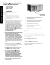
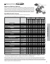
The Outdoor comes standard with the
following additional components:
• Crankcase Heater
• Drain Line Heater
• Weather Hood
• Fan Cycling
(Pressure on 1 fan models, Pressure and Ambient
on 2 fan models).
Standard Installation Procedure
PTT Models
For outdoor use
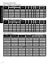
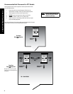
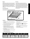
1. Provide a 25" X 25" (medium cabinet) or
25" X 38.5" (large cabinet) opening in the
roof of walk-in cooler or as specied by the
panel manufacturer.
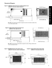
2. Apply silicone caulk around the perimeter of roof
opening. Place the curb on roof of cooler. It is
recommended that the curb be fastened to
the roof panels using non-conductive bolts or
insulating the bolt heads. Bolt heads should be
countersunk or low prole to prevent contact with
the system. (See Figure 1, page 7) Check the
top of the curb with a level. units require
a surface that is within 1° of level or better and no
more than a 5/8" drop per 3 feet
(17mm drop per meter).
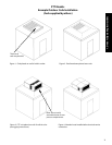
3. Install the membrane onto the roof of the box and
over the curb. Fasten to roof per panel
manufacturer's instructions. The membrane
material should be slit over the evaporator grill
opening the aps allowed to drape into the hole
2" - 4". (See Figure 2, page 7) Care should be taken
during the membrane installation to prevent
bunching or folding which could aect the gasket-
to-curb sealing or trap rainwater adjacent to the
curb.
4. Remove the weather hood from the system.
The compressor compartment cover(s) should be
left in place during lifting/rigging.
5. Place system onto curbing and center over
opening in roof box. (See Figure 3, page 7)
6. It is recommended that the system be
secured to the curb with wood screws. Seal
the screw heads as necessary to prevent
moisture from entering beneath the membrane.
Additional caulk may be applied around the
perimeter of the evaporator box gasket. The
compressor compartment should not be caulked.
7. Install trim pieces (if used) around the ceiling
opening in cooler.
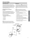
General Safety information:
Do NOT lift the by the weather hood.
This product is not designed to be transported while
installed or operating.
8. Remove compressor compartment cover for
access to electrical box.
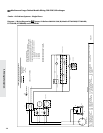
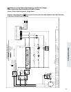
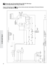
9. Connect power wiring in accordance with all
applicable building and electrical codes.
10. Reinstall condensing unit cover(s).
11. Reinstall the protective weather hood.
(See Figure 4, page 7)
12. Apply power and check for proper operation.
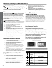
Condensate Drain
Outlet Location
Drain Line
A condensate drain outlet is located on the side of the
compressor compartment. Field piping may be connected
to the outlet provided it is adequately sloped and heated
for freezing weather conditions. There is a drain line "P" trap
located in the PTT unit.