


– 5 –
PNEUMATIC FOOT SWITCH
To install the pneumatic foot switch:
1. Remove screws from the lower front panel.
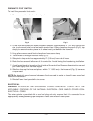
PL-41742
PL-41743
Fig. 2 Fig. 3
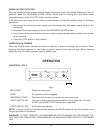
2. On the front of the machine, locate the lower frame rail; approximately 4" (10.2 cm) from the left
side, is a knockout hole for the foot switch control hose. Using a hammer and punch (Fig. 2), tap
sharply to remove knockout piece in the sheet metal just beneath the frame rail.
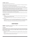
3. Using pliers remove small pinch clamp from hose, save clamp.
4. Thread hose up through knockout hole (Fig. 3).
5. Slide pinch clamp onto hose approximately 2" (5.08 cm) from end of hose.
6. Route the hose around left corner of the control box. Avoid kinking the hose during installation.
7. A small metal nipple is located on the left side of the control box. Remove the protective cap and
push hose tightly over the metal nipple.
8. Slide the clamp up the hose and place it within
1
/4" (0.653 cm) of the hose end (Fig. 3) to ensure
a proper seal.
NOTE: Be absolutely sure hose and clamp are firmly secured to nipple; a loose fit may cause foot
controls to malfunction.
9. Reinstall lower front panel with six screws.
ELECTRICAL
WARNING: ELECTRICAL AND GROUNDING CONNECTIONS MUST COMPLY WITH THE
APPLICABLE PORTIONS OF THE NATIONAL ELECTRICAL CODE AND/OR OTHER LOCAL
ELECTRICAL CODES.
The mixer-grinder is provided with a cord and plug and only requires that it be connected to an
appropriately sized, grounding-type receptacle. Refer to the machine data plate.