


– 6 –
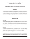
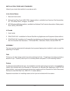
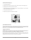
STRAIN RELIEF
FITTING FOR GAS LINE
THIS SIDE ONLY. (To be
supplied by others.)
PL-51194
Provide a restraining device for the gas line to limit movement of the fryer without depending on the
connector and/or any quick-disconnect device or its associated piping to limit movement of the fryer.
Attach the restraint at the rear of the fryer (Fig. 1).
If disconnection of the restraint is necessary, turn off the gas supply before disconnection. Reconnect
this restraint prior to turning the gas supply on and returning the fryer to its originally installed position.
GAS CONNECTION
CAUTION: Gas supply connections and any pipe joint compound must be resistant to the action
of liquified petroleum gases.
Location of the gas inlet is at the lower left rear of the fryer. A gas shutoff valve must be installed in
the gas line ahead of the fryer, as required by codes.
The gas supply line must be at least the equivalent of
1
/2" (12.7mm) iron pipe (or
3
/4" (19.05mm) if using
the optional quick-disconnect flex hose, unless
3
/4" (19.05mm) to
1
/2" (12.7mm) reducing fittings
are utilized). Make sure the pipes are clean and free of obstructions, dirt, and piping compound.
WARNING: PRIOR TO LIGHTING, CHECK ALL JOINTS IN THE GAS SUPPLY LINE FOR LEAKS.
USE SOAP AND WATER SOLUTION. DO NOT USE AN OPEN FLAME.
After piping has been checked for leaks, air should be purged from the gas lines.
GAS PRESSURES AND ORIFICES
The standard orifices are set at 4" (101.6mm) W.C. (Water Column) pressure for natural gas and
10" W.C. pressure for propane. A pressure regulator is supplied as part of the gas control valve.
Fig. 1